


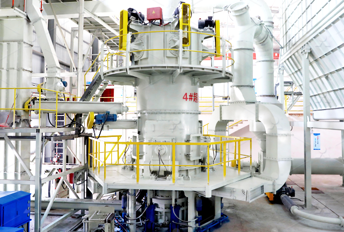
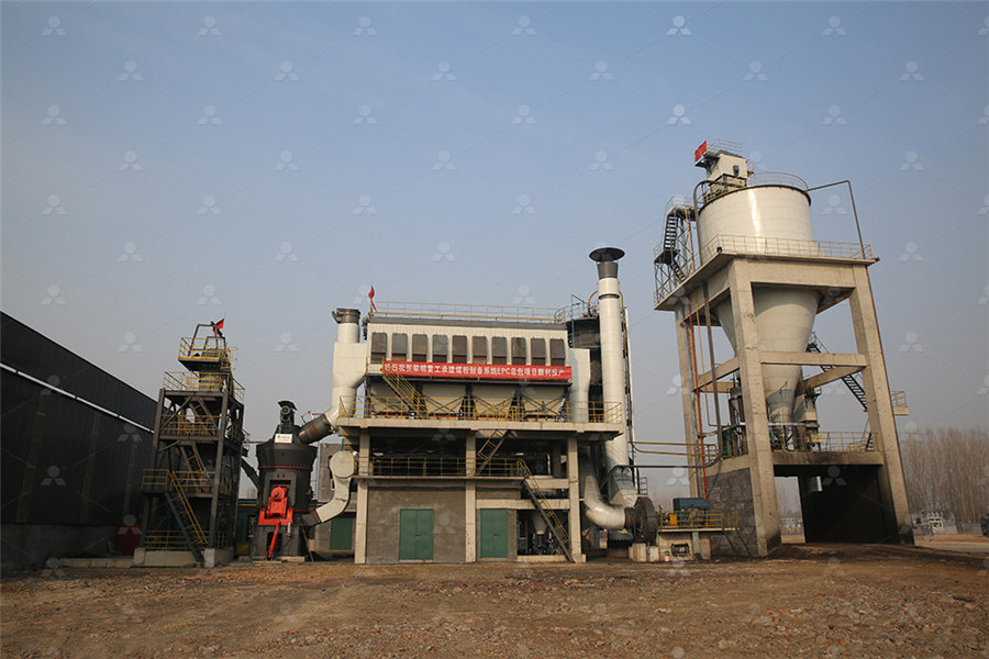
MTW European Type Trapezium Mill
Input size:30-50mm
Capacity: 3-50t/h
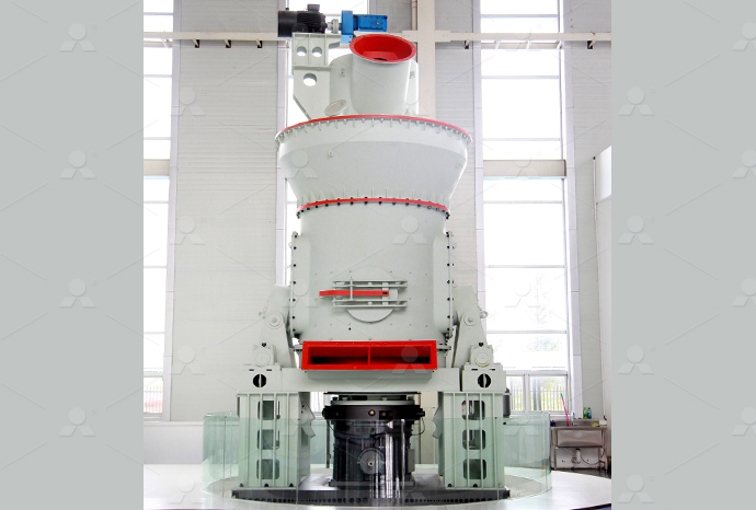
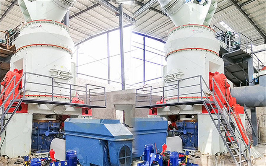
LM Vertical Roller Mill
Input size:38-65mm
Capacity: 13-70t/h
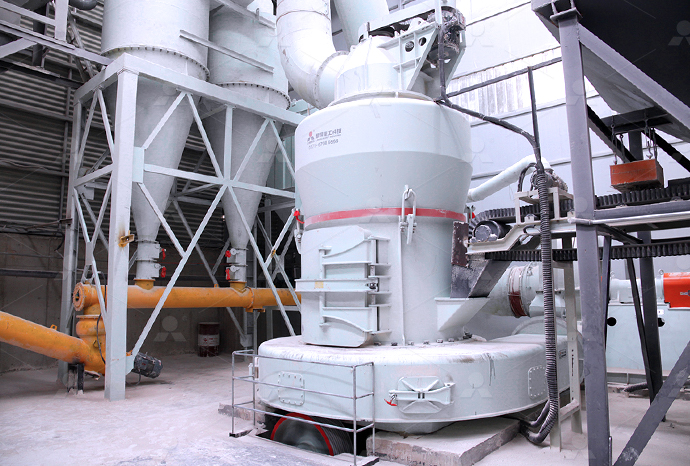
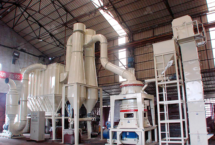
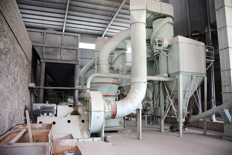
Raymond Mill
Input size:20-30mm
Capacity: 0.8-9.5t/h
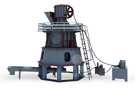
Sand powder vertical mill
Input size:30-55mm
Capacity: 30-900t/h
LUM series superfine vertical roller grinding mill
Input size:10-20mm
Capacity: 5-18t/h
MW Micro Powder Mill
Input size:≤20mm
Capacity: 0.5-12t/h

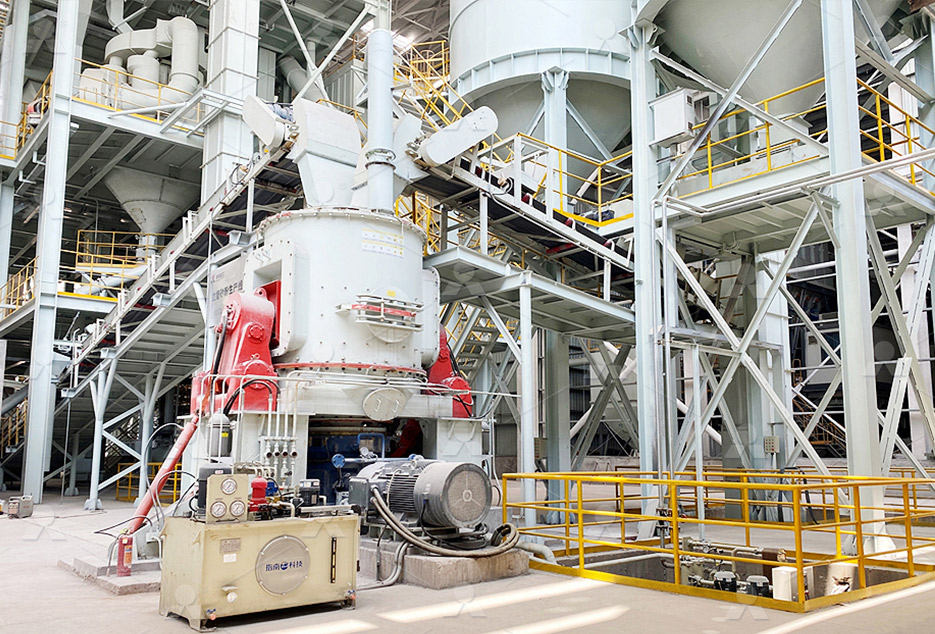
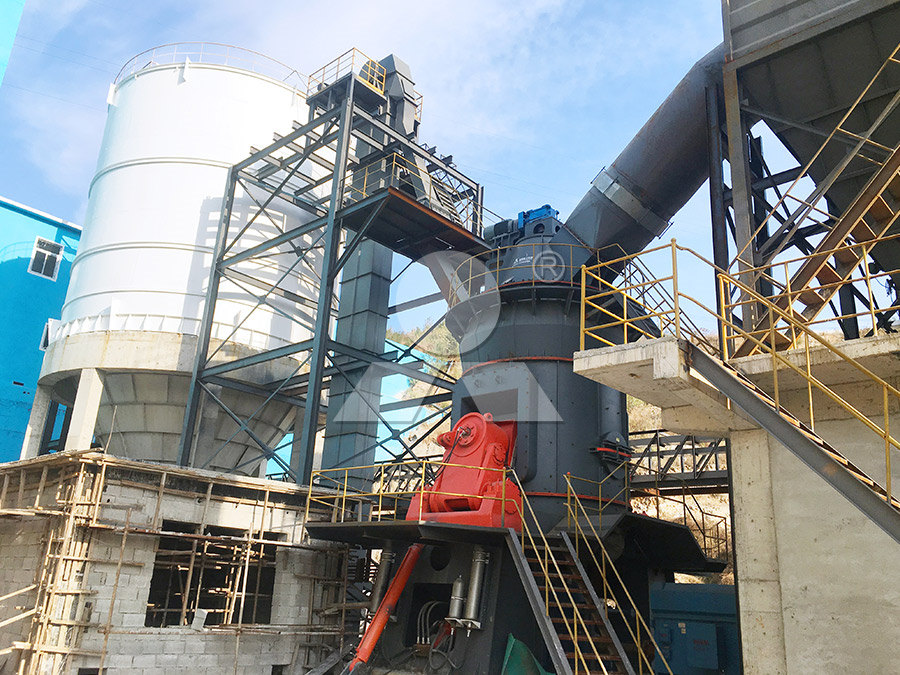
LM Vertical Slag Mill
Input size:38-65mm
Capacity: 7-100t/h
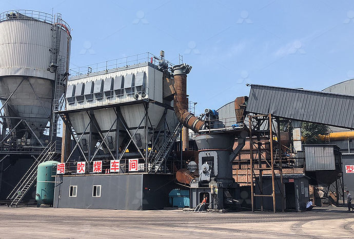
LM Vertical Coal Mill
Input size:≤50mm
Capacity: 5-100t/h
TGM Trapezium Mill
Input size:25-40mm
Capacity: 3-36t/h

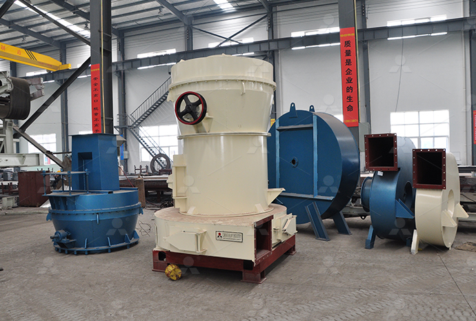
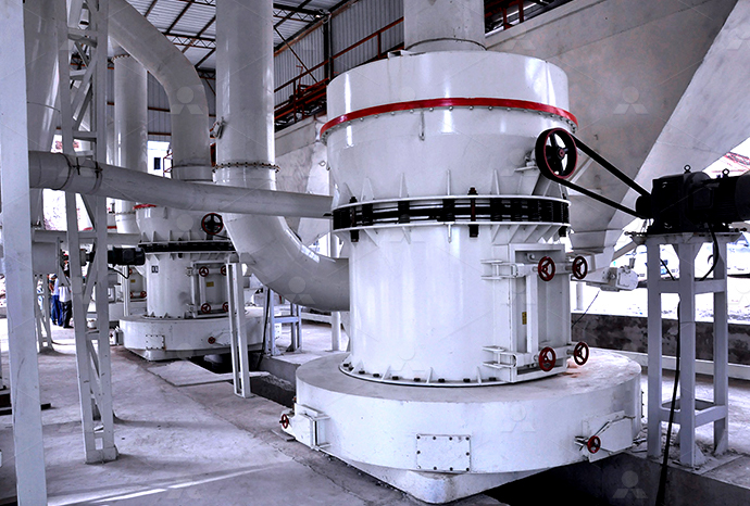
MB5X Pendulum Roller Grinding Mill
Input size:25-55mm
Capacity: 4-100t/h
Straight-Through Centrifugal Mill
Input size:30-40mm
Capacity: 15-45t/h
Zhangjiakou pneumatic grinding machine gas circuit diagram
PNEUMATICS CIRCUIT DESIGN PSA
Question: Design the pneumatic circuit diagram based on task given A doubleacting cylinder is used to clamp components on a drill machine Upon operation of a push button and its in start Our main objective is Experimental study on Pneumatic Grinding Machine This study gives the better result of surface finishing of various material applications Grinding process is most PNEUMATIC EQUIPMENT IN MASS PRODUCTON SYSTEM FOR 2014年1月11日 The document discusses basic pneumatic circuitry and components for control and automation It covers pneumatic symbols, circuit layout principles, and examples of Pneumatic circuits PPT SlideSharePneumaticCircuitDiagramSortingpdf Free download as PDF File (pdf), Text File (txt) or view presentation slides online The document contains a diagram with labels in German It Pneumatic Circuit Diagram Sorting PDF PDF Pneumatics Gas
Schematic diagram of pneumatic circuit (1) Air Source, (3) (5) (16
It consists of doubleacting cylinder, force sensor, displacement sensor, electric proportional valve, pneumatic triple parts (air pressure reducing valve, filter, oil mist device), air source A pneumatic system schematic diagram is a visual representation of the various components and connections in a pneumatic system It provides a clear and concise overview of how The Ultimate Guide to Understanding Pneumatic System This part of ISO 1219 supplements ISO 12191 and ISO 12192 by specifying rules for the generation and combination of symbols of connectable components in circuit diagrams Using ISO 12193:2016(en), Fluid power systems and componentsThis white paper examines pneumatic design best practices, and then presents four basic pneumatic circuits (Table 1) commonly used in machine automation While there are many Basic Pneumatic Circuits AutomationDirect
Pneumatics and Hydraulics Philadelphia University
Circuit diagram •The circuit diagram shows signal flow and the relationship between components and the air connections •There is no mechanical layout representation with the circuit Hydraulics Pneumatics Chapter 3: Pneumatics (Design of Pneumatic Circuit) by Dr Mohd Fadzil Faisae Faculty of Mechanical Engineering raulics Pneumatics Chapter 3: Pneumatics (Design of A surface grinding machine is a machine tool used to provide precision ground surfaces, either to a critical size or for the surface finish The typical precision of a surface grinder depends on the type and usage, however, a typical precision for surface Understanding the Surface Grinding Machine: An InDepth DiagramDiagrams include sequence diagrams, flow charts, entity relationship diagrams, cloud architecture diagrams, data flow diagrams, network diagrams, and more Brought to you by the folks at Want this for your team? Let's chat if your team has a specific diagramming workflow to automateDiagramGPT – AI diagram generator
.jpg)
14 Types of Grinding Machines [Working, Diagram
2021年11月23日 This is a small grinder operated with electric power It can be easily carried anywhere Grinding can be done by holding it in hand It is used for cleaning heavy welding jobs On one end of the motor shaft, a grinding wheel 2016年3月21日 In Figure 2B (a 3position valve), the valve has both solenoids and ‘spring return’ actuators on both sides, the spring return actuators will return the valve to the center position but only IF neither of the solenoids is active: With this 3position valve, the center flow box shows the flow path when neither actuator is active and the springs are holding the valve in the center Pneumatic Circuit Symbols ExplainedThis machine is functional but the cost was high and hence there could be cheaper alternatives Bankole I Oladapo et al in their paper "Experimental analysis of electropneumatic optimization of The schematic diagram of the electropneumatic circuit in the 2019年11月18日 Drawing a pneumatic circuit diagram is a great way to visualize and troubleshoot pneumatic systems, which use compressed air to power mechanical devices While drawing a pneumatic circuit diagram is not overly complicated, it does require some knowledge of standard symbols, components, and the basics of pneumaticsHow To Draw Pneumatic Circuit Diagram Wiring Digital and
R)8OC`6F[ZIB.jpg)
Anesthesia Gas Machine Components and systems Introduction
The basic pneumaticmechanical design of the anesthesia gas machine had become familiar to a generation of providers The basic design has been called upon to perform more complicated functions, with the advent of computercontrolled monitors into the operating room, especially pulse oximetry, capnography, and gas analysisA pneumatic diagram, also known as a pneumatic circuit diagram or pneumatic schematic, is an essential tool for understanding and designing these systems It visually represents the components, connections, and flow of compressed air or gases within a pneumatic systemUnderstanding Pneumatic Diagrams: A Complete GuideThe hydraulic circuit for surface grinding machine utilizes a power pack to supply pressurized oil, one pilotoperated direction control valve which decides the direction of the flow of pressurized oil and a doubleacting cylinder with the double piston rodHydraulic Circuit for Surface Grinding Machine Engineering ArenaA pneumatic system schematic diagram is a visual representation of the various components and their interconnections in a pneumatic system Pneumatic systems use compressed air or gas to power and control the movement of mechanical components, making them widely used in industries such as manufacturing, automation, and transportation systemsThe Ultimate Guide to Understanding Pneumatic System Schematic Diagrams
.jpg)
Pneumatic Circuit Diagram Pdf
2017年9月27日 With a pneumatic circuit diagram PDF, one can quickly understand the layout of a system, including its operation and the direction of the flow of air or gas In addition to being useful for students and engineers, 111 Pneumatic circuit diagram for one cylinder based on: a Direct control b Indirect control 112 Pneumatic circuit diagram: a Dual pressure valve (AND Function) b Shuttle valve (OR Function) c 5/2way double pilot valve d Pressure sequence valve e Time delay valve 113 Design the pneumatic circuit diagram based on task givenPNEUMATICS CIRCUIT DESIGN PSAPneumatic Circuits Hydraulic Circuits Pneumatic Circuits 15 Applications: Automatic lathe Drilling machines Grinding machines Shaping machines Crushers Fork lift trucks Dumpers Truck loaders Bulldozers Hydraulic press 15 Applications: Automatic machines for holding, gripping, feeding, bottling, wrapping, packaging etcCHAPTER 6 HYDRO PNEUMATIC SYSTEMS CIRCUITS By Prof Download scientific diagram Schematic diagram of the grinding machine and instrumentation from publication: Predicting Surface Roughness in Grinding Using Neural Networks The technique of Schematic diagram of the grinding machine and instrumentation
Design of hydraulic pneumatic control system for rail grinding car
2022年12月1日 According to the accuracy requirements of the rail grinding car, the pneumatic servo schematic diagram of the grinding 41 Simulation and analysis of pneumatic grinding wheel contr ol circuit Processing tubes from poly (llactic acid) (PLLA) by stretch blow moulding (SBM) is used in the manufacture of bioresorbable vascular scaffolds (BVS) to improve their mechanical performanceSchematic diagram of the ISBM pneumatic systemFlowchart Maker and Online Diagram Software drawio is free online diagram software You can use it as a flowchart maker, network diagram software, to create UML online, as an ER diagram tool, to design database schema, to build BPMN online, as a circuit diagram maker, and more drawio can import vsdx, Gliffy™ and Lucidchart™ files Flowchart Maker Online Diagram SoftwareThe hydraulic circuit for a milling machine is comparatively different from the hydraulic circuit of the surface grinding machine and hydraulic circuit of the shaper machineThis is because the table movement in milling operation is comparatively slower Also, the different feeds or you can say adjustable feeds are required for milling different types of workHydraulic Circuit for Milling Machine Explained In Details
.jpg)
10 Pneumatic Schematic Examples for Easy Understanding
Pneumatic Logic Circuits Pneumatic logic circuits are systems that use compressed air or gas to control and operate various components in an automated system These circuits are commonly used in industries such as manufacturing, automotive, and aerospace for their simplicity, reliability, and costeffectivenessThe hydropneumatic circuit has been developed for the neardry WEDM as shown in Fig 1 It is made by a fluid tank, biaxial hoses, a nozzle, flow control valves and the pressure gaugesSchematic diagram of hydropneumatic circuit for Anaesthetic Machine Back to Front By the perioperativeCPD team The most important piece of equipment that the anaesthetist uses is the anaesthesia machine The basic function of an anaesthesia machine is to prepare a gas mixture of precisely known, but variable composition The gas mixture can then be delivered to a breathing systemAnaesthetic machine basics 2021 perioperativeCPDDownload scientific diagram Circuit diagram of the pneumatic system of the smallsized air compressor from publication: Research on the controllability and energy saving of the pneumatic direct Circuit diagram of the pneumatic system of the
Basic Pneumatic Circuits LibraryAutomationdirect
basic pneumatic circuits (Table 1) commonly used in machine automation While there are many variations, these pneumatic circuits combine basic pneumatic components to create functional and reliable pneumatic circuits Pneumatic Design Best Practices Before discussing these four basic pneumatic circuits, it’s best to review best practices2017年12月19日 Pneumatic actuators Fluid actuators are used to convert fluid energy into mechanical linear motion For more information about reading hydraulic and pneumatic circuit diagrams, read the next article in this series which describes sample hydraulic circuits, or contact your Valmet representativeReading fluids circuit diagrams hydraulic pneumatic symbols 2024年9月17日 Pneumatic solenoid valves come in various types, each suited for specific applications Table 2 shows common types of pneumatic solenoid valves, including 2 position pneumatic solenoid valve diagrams and 3 position pneumatic solenoid valve diagrams Table 2: Types of pneumatic solenoid valves and their diagramsPneumatic Solenoid Valve Diagram Guide Tameson2021年10月13日 The following four pneumatic circuits can be used for air preparation, doubleacting cylinders, continuous cycling and hand control applications They can also be subsystems in larger circuits Air Preparation Before compressed air is used in a pneumatic device, it must be properly prepared so that it does not damage components4 Basic Pneumatic Circuits Power Motion
.jpg)
Design and Fabrication of Pneumatic Automatic Bending Machine
40 P a g e Design and Fabrication of Pneumatic Automatic Bending Machine Krushna Kale1, Tejas Chondhe 2, Satish Kadam3, Nanasaheb Zende4 1,2,3,4 UG Student, Mechanical Engineering, Trinity Academy of Engineering, Pune, India 1Corresponding, Author : krushnakale0007@gmail Abstract – This study is focusing on design and Fabrication of Components of a Pneumatic Circuit Diagram In a pneumatic circuit diagram, several components are used to create a functioning system Each component plays a specific role in controlling the flow of compressed air and ensuring the proper operation of pneumatic devices Here are some key components commonly found in a pneumatic circuit diagram: 1How to Design an Effective Pneumatic Circuit Diagram for a Separate machine for metal rod bending and cutting machine for avoiding this problem we can construct the new machine that is pneumatic rod bending and cutting machine the rod bending operation can be perform with help of pneumatic cylinder, and cutting operation will be perform with help of cutter 31 Block diagram of a pneumatic bending machineFABRICATION OF PNEUMATIC ROD BENDING MACHINE AND 2022年6月7日 To further understand pneumatic valves, we will explore the different types of pneumatic valves and how they are used So let’s get started Don’t Miss: Different Types of Pumps and Their Working Uses Types of Pneumatic Valves: Diagram, Types, Working
.jpg)
PNEUMATICS CIRCUIT DESIGN PSA
111 Pneumatic circuit diagram for one cylinder based on: a Direct control b Indirect control 112 Pneumatic circuit diagram: a Dual pressure valve (AND Function) b Shuttle valve (OR Function) c 5/2way double pilot valve d Pressure sequence valve e Time delay valve 113 Design the pneumatic circuit diagram based on task given2018年3月10日 Reading Fluids Circuit Diagrams Pneumatic Examples Pneumatic Circuit Diagrams Learnchannel Tv Com Reading Fluids Circuit Diagrams Hydraulic Pneumatic Symbols Solved Figure Below Provides A Basic Pneumatic Schematic DiagramDownload scientific diagram Pneumatic circuit schematic diagram of drilling bit feed times can be preselected ffi¼, Stepper module; 1, twoposition fourway change valve; 2 and 3, two Pneumatic circuit schematic diagram of drilling bit feed times ANESTHESIA GAS MACHINE> COMPONENTS SYSTEMS> DELIVERY> BREATHING CIRCUITS Classification; Breathing circuits Non rebreathing (Mapleson and Bain) The Bain has been shown to add more heat and humidity to inhaled gases than other Mapleson circuits Diagram of the Mapleson D how it works Click on the thumbnail, or on the underlined text, Anesthesia Gas Machine Breathing circuits University of Detroit
.jpg)
Pneumatic Circuit Diagram Examples Wiring Draw
2022年7月29日 If you’re an engineer, technician, or other professional who is interested in pneumatic systems, then knowing how to read and interpret pneumatic circuit diagrams should be a top priority After all, the diagrams provide important information about how the components of a system interact with each other, and how they should be assembled to perform a specific taskDownload scientific diagram Grinding and classification circuit diagram from publication: Approximation of Partition Curves for Electromagnetic Mill with Inertial Classifier – Case study The Grinding and classification circuit diagramIn smallscale industries and automobile maintenance shops, there are frequent needs of tightening and loosening in screws, drilling, boring, grinding machine Huge and complicated designed parts cannot be machined in ordinary machine Further for every operation separate machine is requiredPNEUMATIC AUTO FEED DRILLING MACHINE MECHANICAL 2014年5月29日 Fig: ELECTRONIC CONTROL TIMING UNIT Fig: Diagram of Automatic Pneumatic Grinding Machine WORKING PRINCIPLE PNEUMATIC CIRCUIT: Fig: Pneumatic circuit Since pneumatic circuit plays a vital role in this device, it is very necessary to explain the working of this circuitAutomatic Pneumatic Grinding Machine: Working Principle and
.jpg)
Hydraulic circuit for a surface grinding machine
HYDRAULIC CIRCUIT FOR A SURFACE GRINDING MACHINE 1 Functional and Operational Requirements • In a surface grinding machine (or a milling machine) the work piece is clamped on the machine table and the machine table is made to reciprocate continuously with same speed during both forward and return strokes The continuous reciprocation of machine table is