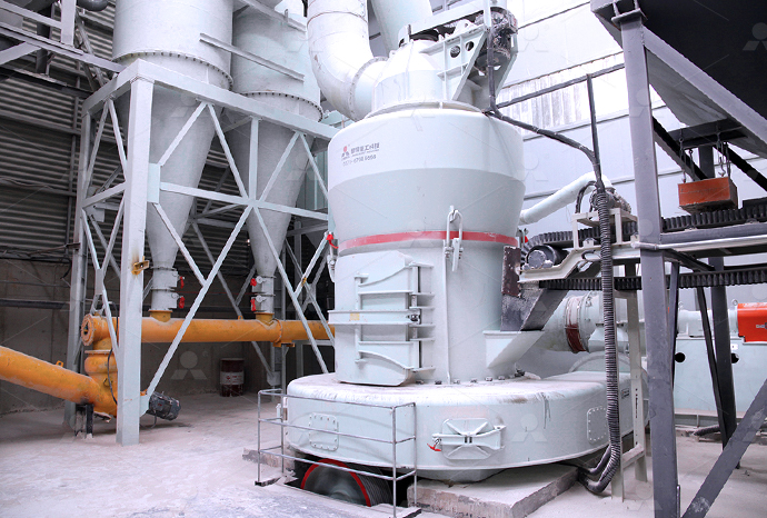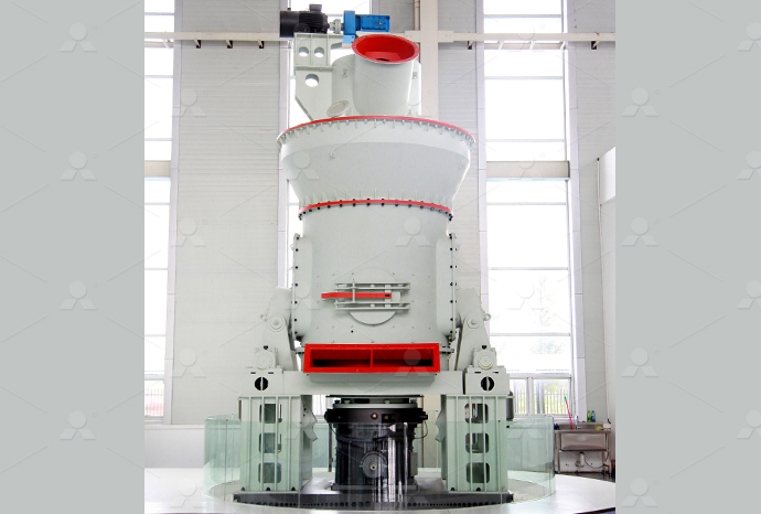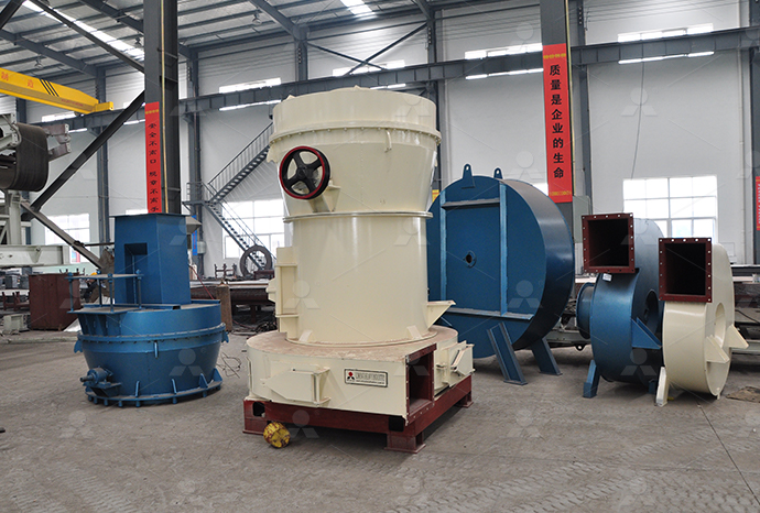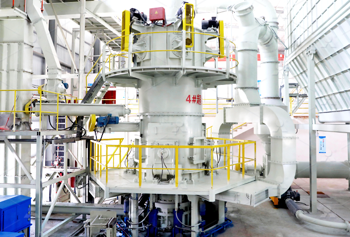
Hydraulic barite mill power wiring schematic diagram Load
.jpg)
Circuit diagram HAWE Hydraulik
All hydraulic units and their connections must be shown on the circuit diagram The hydraulic schematic forms the basis of the pipework of the system and –– together with the function This manual provides descriptive operation and maintenance instructions for standard Hydraulic Power Units manufactured by the Hydraulic Pump and Power Systems Division of Parker Hydraulic Power Units Parker Hannifin CorporationInstallation: 12 vdc, Double Acting (Power UP / Power DOWN) Unit Diagram A1 1 Install 9/1618 SAE ORB, SAE #6, hydraulic fittings into ports “A” and “B” Torque fittings to 18 lbft 2 Installation: 12 vdc, Double Acting (Power UP / Power DOWN) UnitExplain various hydraulic circuits to control singleacting and doubleacting cylinders Explain a regenerative circuit and determine the loadcarrying capacities Describe the working of a Lecture 24 HYDRAULIC CIRCUIT DESIGN AND ANALYSIS
.jpg)
Structural schematic diagram of load Download Scientific Diagram
As the core control system of a rolling mill, the hydraulic automatic gauge control (HAGC) system is key to ensuring a rolling process with high speed, high precision and high reliabilityHYDRAULIC PUMPS WHAT DETERMINES THE TYPE OF PUMP • Flow Required • RPM’s the Pump will operate • Hydraulic System Pressure Requirement • Type of Hydraulic Valve [Open Training Basic Hydraulics Parker HannifinAttach One Of The Two Coil Wires From Each Coil To Either The (Red) Or (Green) Wires In The Control Cord The Remaining Wires (One From Each Coil) Will Be Grounded To Valve Body Bucher Hyd Models2020年6月15日 Make sure the power pack has been properly connected with the appropriate size wiring Chart shows recommend wire size Never use smaller than 4 gauge power and STARTUP / INSTALLATION REFERENCE FORCE America, Inc

Wiring diagram for Mettler Toledo load cells: A comprehensive
Wiring Diagram for SinglePoint Load Cell The wiring diagram for a singlepoint load cell is a crucial component in any weighing system It provides a visual representation of how the load cell should be connected to other components in the system, Covers: Case 821E Tier 2 Wheel Loader Pages: 3 Format: PDF Compatible with: Windows/Mac/Tablet Notes: High resolution foldout diagram/schematic download The Case 821E Tier 2 Wheel Loader Hydraulic + Wiring Diagram provides information for the correct servicing and troubleshooting of electrical and hydraulic systems and is essential for all Case 821E Tier 2 Wheel Loader Hydraulic + Wiring DiagramDownload scientific diagram Digital hydraulic schematic diagram of working device of loader; 1Digital pump; 2Oil source valve; 3Pilot valve; 4Boom cylinder; 5Multiway valve; 6Bucket Digital hydraulic schematic diagram of working Covers: Case 410, 420, 420CT Skid Steer/Track Loader (including Tier 3 Cab Upgrade) Pages: 8 Format: PDF Compatible with: Windows/Mac/Tablet Notes: High resolution foldout diagram/schematic download The Case 410, 420, 420CT Skid Steer/Track Loader Hydraulic + Wiring Diagram provides information for the correct servicing and troubleshooting of electrical Case 410, 420, 420CT Skid Steer/Track Loader Hydraulic + Wiring Diagram

Hydraulic Circuit Diagram With Explanation Wiring Draw And Schematic
2023年3月21日 Basic Hydraulic System Components Parts Design Circuit Diagram Hydraulic Machine System Diagram Harsle Create A Pneumatic Or Hydraulic Control System Diagram The True Value Of Hydraulic Circuit Diagrams Schematic Diagram Of The Hydraulic System Scientific An Introduction To Diffe Hydraulic Circuits 2 Hydraulic Circuit Diagram For A Press This page provides the chapter on basic fluid power diagrams and fluid power systems from the US Navy's fluid power training course, NAVEDTRA 14105A, "Fluid Power," Naval Education and Training Professional Development and Technology Center, July 2015 Other related chapters from the Navy's fluid power training course can be seen to the rightBasic Diagrams and Systems Engineering LibraryCovers: Case 621E Tier 3 Wheel Loader Pages: 3 Format: PDF Compatible with: Windows/Mac/Tablet Notes: High resolution foldout diagram/schematic download The Case 621E Tier 3 Wheel Loader Hydraulic + Wiring Diagram provides information for the correct servicing and troubleshooting of electrical and hydraulic systems and is essential for all Case 621E Wheel Loader Hydraulic + Wiring Diagram Schematics StepbyStep Guide to Wiring a Bennett Hydraulic Trim Tab Switch Wiring a Bennett hydraulic trim tab switch is a relatively simple process that can be completed in a few steps To ensure proper installation and functionality, it is important to follow these stepbystep instructions Step 1: Gather the necessary materialsStepbyStep Guide: Wiring Diagram for Bennett Hydraulic Trim
.jpg)
How To Wire A Hydraulic Solenoid Valve » Wiring Work
2021年4月12日 Book 2 Chapter 8 Directional Control Valves Power Motion Coils For Solenoid Valves Versatile And Easy To Install Danfoss Hydraulic Solenoid Selector Diverter Valve 30 Gpm 12v Dc Six Major Problems Of Hydraulic Solenoid Valves Finotek Schematic Of A Hydraulic Solenoid Valve Scientific Diagram How To Wire A Solenoid ValveFigure 27 Simple Hydraulic Power System Figure 28 Line Diagram of Simple Hydraulic Power System With an understanding of the principles involved in reading fluid power diagram, any diagram can be interpreted Figure 29 shows Hydraulic and Pneumatic PID Diagrams and 2023年3月18日 The True Value Of Hydraulic Circuit Diagrams The Real Value Of Hydraulic Circuit Diagrams Fluid Power Journal Hydraulic Symbology 102 Understanding Basic Fluid Power Schematics Drawing Basic Hydraulic How To Understand Hydraulic Circuit Diagram2020年8月13日 In this article, we’ll provide an overview of the visual language of hydraulic schematics and explain how to read them We’ll also share a few tips for troubleshooting when you come across any issues Hydraulic schematics are How To Read Basic Hydraulic Schematics » Wiring
.jpg)
A Breakdown of a Hydraulic Power Pack Circuit Diagram All Wiring
What does a hydraulic power pack circuit diagram look like? A hydraulic power pack circuit diagram typically includes symbols representing the various components of the power pack, such as the pump, reservoir, motor, valves, filters, and any other necessary components It also shows the flow paths of hydraulic fluid and the electrical connectionsPK 50002 (Hydraulic Diagram) Free download as PDF File (pdf), Text File (txt) or read online for free This document contains a hydraulic diagram for a crane It includes a key for various signs and symbols used in hydraulic diagrams, such as signs for different crane components and devices It also includes a key for electrical triggers and feedback signals related to crane PK 50002 (Hydraulic Diagram) PDF Crane (Machine) Machines16) Cycle hydraulics on bale loader, in and out, open and close, two or three time s add oil as needed until all air is removed 17) System should hold approximately 3 to 3—1/2 gallons of hydraulic oil 18) Check for leaks with hydraulic pump running and with hydraulic pump off 19) Recheck all mountings, fittings and electrical connections Resler Industrie's IncHydraulic Mid Inlets 29 Power Beyond 30 Open Center Schematic 31 Closed Center LS Schematic 32 Horse Power Consumption 33 Hydraulic Cylinders 34 Single Acting Double Acting Cylinders 35 Bleeding Air 36 Hydraulic Motor Types 37 How Motors Work 38 Filtration 39 How Filters are Selected 40 PTO Types 41 Manual PTO’s 42Training Basic Hydraulics Parker Hannifin
.jpg)
Hydraulic system schematic diagram of loader actuator 1 Load
Download scientific diagram Hydraulic system schematic diagram of loader actuator 1 Loadsensing pump 2 Auxiliary pump 3 Engine 4 Safety valve 5 Relief 2023年1月5日 What Is a Solar Panel Wiring Diagram? A solar panel wiring diagram (also known as a solar panel schematic) is a technical sketch detailing what equipment you need for a solar system as well as how everything should connect together There’s no such thing as a single correct diagram — several wiring configurations can produce the same resultSolar Panel Wiring Diagram for All Setups [+ PDFs] – SolartapHydraulic schematic symbols are used to represent various components and functions in hydraulic systems Understanding these symbols is essential for interpreting hydraulic schematics and designing hydraulic circuits Here are some commonly used hydraulic schematic symbols: Pump: The pump is represented by a circle with an arrow pointing inwardDecoding Hydraulic Pictorial Symbols: Simplifying the Language Hydraulic schematic symbols are standardized graphical representations used to depict the components of hydraulic systems on schematic diagrams allowing the spring or external load to return the piston to This international standard Hydraulic Schematic Symbols : How To Read A
.jpg)
Introduction To Hydraulic And Pneumatic Schematic Diagrams
2019年8月10日 Chapter 5 Pneumatic And Hydraulic Systems Power Motion Hydraulic And Pneumatic P Id Diagrams Schematics Inst Tools Chapter 5 Pneumatic And Hydraulic Systems Power Motion Tutorial 5 Electric And Pneumatic Circuits User Manual Pneumatic Circuit Symbols Explained Library Automationdirect Basic Pneumatic Circuits Tech Briefs Reading Covers: Case 1840 Skid Steer Loader Pages: 183 Format: PDF Compatible with: Windows/Mac/Tablet Notes: High resolution foldout diagram/schematic download The Case 1840 Skid Steer Loader Hydraulic Wiring Diagram provides Case 1840 Skid Steer Loader Hydraulic Wiring Exploring the Inner Workings of a Hi Lift Jack: Comprehensive Parts Diagram; Complete Wiring Diagram for 2002 Yamaha V Star 1100; Wiring Diagram for 9 Pin Deutsch Connector; Understanding the Inner Workings of Hot Tubs: A Comprehensive Diagram; Wiring diagram for Aiphone JO1FD intercom system; EasytoFollow Serpentine Belt Diagram for 2000 The Comprehensive Guide to Understanding Hydraulic Jack Schematic DiagramsDownload scientific diagram Schematic diagram of the loadsensing hydraulic system with multiway valve and pressurecompensated valve 1quantitative pump; 2variable frequency motor; 3filter Schematic diagram of the loadsensing hydraulic system with
.jpg)
Hydraulic Schematic Diagram Symbols
2022年7月5日 Hydraulic Symbols Understanding Basic Fluid Power Schematics Solved 2 20 Points For The Following Hydraulic Circuits Chegg Com Hydraulic Symbols Hydraulic And Pneumatic P Id Diagrams Schematics Inst Tools The True Value Of Hydraulic Circuit Diagrams Reading Fluids Circuit Diagrams Hydraulic Pneumatic Symbols Basic Hydraulic System Top Sellers Case 450, 450CT, 465 Series 3 Skid Steer/Track Loader Hydraulic + Wiring Diagram $ 999; Cummins ISX15 CM2250 Wiring Diagram PDF $ 999; Cummins ISX CM871 Engine Wiring Diagram PDF $ 999; Freightliner Cascadia Truck Electrical Wiring Diagrams $ 1999; New Holland LS160, LS170 Skid Steer Loader Wiring Diagram PDF $ 1999Case 921E Wheel Loader Hydraulic + Wiring Diagram Schematics How to Interpret and Use the Bobcat 863 Wiring Schematic If you own a Bobcat 863 skid steer loader, understanding its wiring schematic can be extremely helpful for troubleshooting and repairing electrical issues The wiring schematic provides a detailed diagram of the electrical system, showing the connections and components involvedThe Complete Guide to Understanding Bobcat 863 Wiring SchematicHigh power density: Hydraulic systems can generate high levels of force and power in a compact and lightweight design, making them ideal for applications where space and weight are limited Flexible and precise control: Hydraulic systems allow for precise control over the speed, direction, and force of the actuator, providing flexibility and accuracy in operationsUncovering the Mechanics: A Visual Guide to Hydraulic Jack Schematics
.jpg)
Caterpillar Wheel Loader 966H 972H Workshop Repair
2019年1月10日 INSTANT DOWNLOAD Complete workshop service manual with electrical wiring diagrams for Caterpillar Wheel Loader 966H 972H It's the same service Schematic (966H 972H Wheel Loader Hydraulic System) RENR8829 RENR8846 – Troubleshooting (966H Wheel Loader 972H Wheel Loader Power Train) RENR8847 – Disassembly Covers: Case 450, 450CT, 465 Series 3 Skid Steer/Track Loader (including Tier 3 Cab Upgrade) Pages: 6 Format: PDF Compatible with: Windows/Mac/Tablet Notes: High resolution foldout diagram/schematic download The Case 450, 450CT, 465 Series 3 Skid Steer/Track Loader Hydraulic + Wiring Diagram provides information for the correct servicing and troubleshooting Case 450, 450CT, 465 Series 3 Skid Steer/Track Loader Hydraulic Covers: Case 430, 440, 440CT Skid Steer/Track Loader Pages: 6 Format: PDF Compatible with: Windows/Mac/Tablet Notes: High resolution foldout diagram/schematic download The Case 430, 440, 440CT Skid Steer/Track Loader Hydraulic + Wiring Diagram provides information for the correct servicing and troubleshooting of electrical and hydraulic systems and is essential for all Case 430, 440, 440CT Skid Steer/Track Loader Hydraulic + Wiring DiagramDownload scientific diagram Structural schematic diagram of load from publication: Bifurcation Characteristic Research on the Load Vertical Vibration of a Hydraulic Automatic Gauge Control Structural schematic diagram of load Download
.jpg)
Hydraulic system diagram: practical tips and schematics
2024年4月19日 Hydraulic Systems functioning: The basics In general, hydraulic systems for civilian use are divided into two main types: Water supply and distribution (hot and cold), coming from the water supply system or tank;; Drainage of black water, into the municipal sewer system, or, in its absence, into a septic tank The water conveyed in the drainage system can be 2017年11月30日 Usliccx 4 Wires Dump Trailer Remote Control Switch 12v Dc Hydraulic Power Pump Unit For Double Acting Up And Down Controller Truck Lift Gate Tipper Hoist Online In Taiwan 12 Volt Dc 2 0 Gpm 1000 Psi Kti Dc3147 Single Acting Hyd Power Unit Units Hydraulic Hydraulics Www Surpluscenter Com Dc Power Unit Troubleshooting Guide Kti Hydraulics IncKti Hydraulic Pump Wiring DiagramDownload scientific diagram Simplified schematic of a hydroelectric power plant from publication: Modeling Hydro Power Plants and Tuning Hydro Governors as an Educational Guideline Appropriate Simplified schematic of a hydroelectric power plantInstallation: 12 vdc, Double Acting (Power UP / Power DOWN) Unit Diagram A1 1 Install 9/1618 SAE ORB, SAE #6, hydraulic fittings into ports “A” and “B” Torque fittings to 18 lbft 2 Remove the twobutton pendant from the power unit at the quick disconnect 3 Mount the Power Unit using two, 3/816 UNC mounting bolts (diagram A3) 4Installation: 12 vdc, Double Acting (Power UP / Power DOWN) Unit

The Best Way to Read a Hydraulic Schematic Mentored Engineer
2022年6月8日 Pneumatics will have a few extra components that we don’t use in hydraulics such as oilers, air dryers and Venturi Vacuums, but they are similar Let’s get started 1 Identifying the line types In a hydraulic schematic, each line type has a unique meaning In addition, colors can be added to indicate purpose of the line2024年3月20日 Find schematics, manuals, specifications and diagrams for ELECTRICAL ELECTROHYDRAULIC, HIGH FLOW (L223L230,C232,C238) Find genuine OEM parts for your needs Log In or Create an AccountNew Holland Agriculture Schematic, Manuals, Specifications and 2024年6月18日 On the other hand, if you’re connecting 42 x EcoFlow 400W rigid solar panels to 3 x DELTA Pro Ultra Inverters + Home Backup batteries, the diagram will be considerably more complicated For solar panel arrays with more than a few panels, you’re going to need to take the particulars of your installation area into account to optimize performanceThe Complete Guide to Solar Panel Wiring Diagrams EcoFlow


