


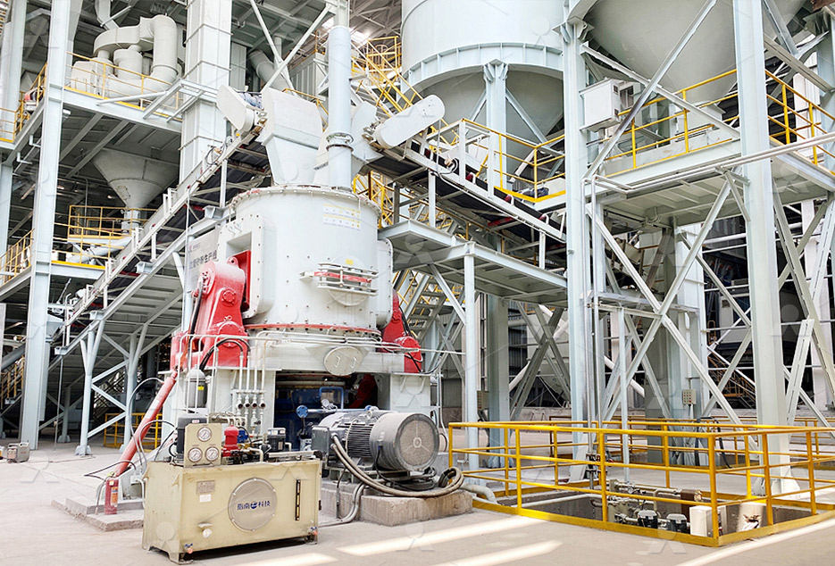
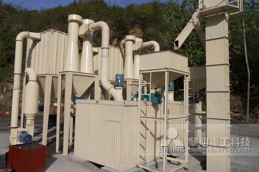
MTW European Type Trapezium Mill
Input size:30-50mm
Capacity: 3-50t/h
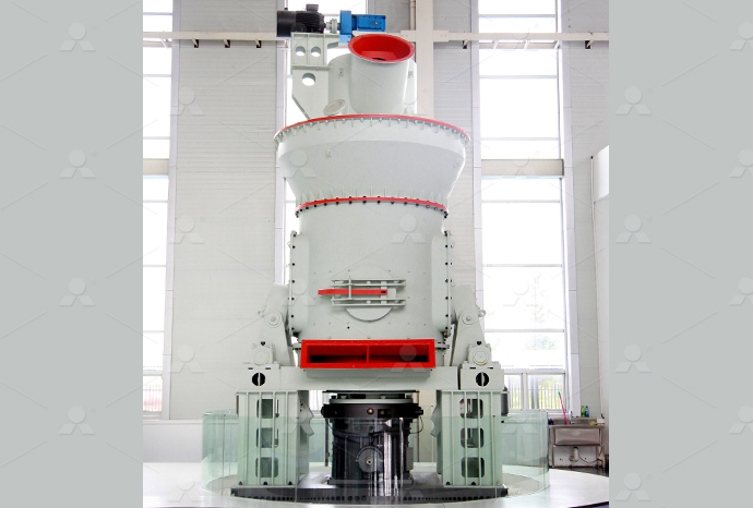
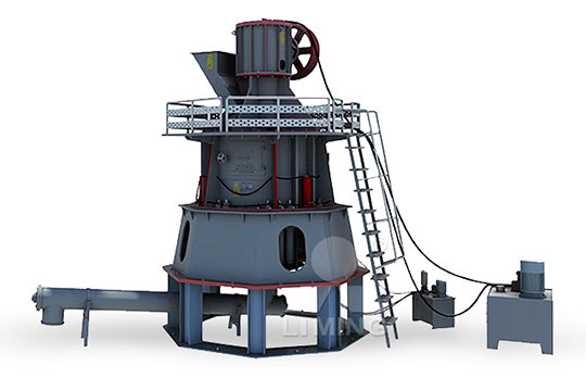
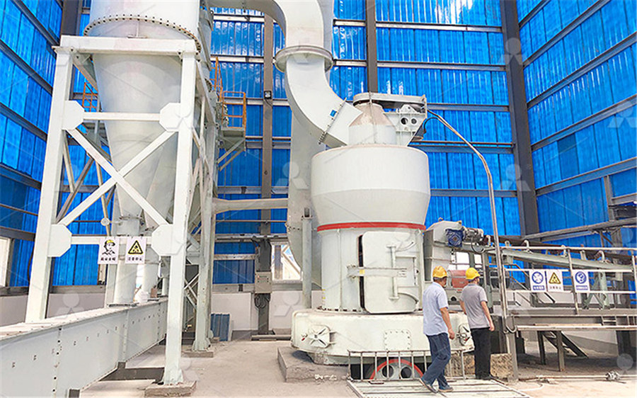
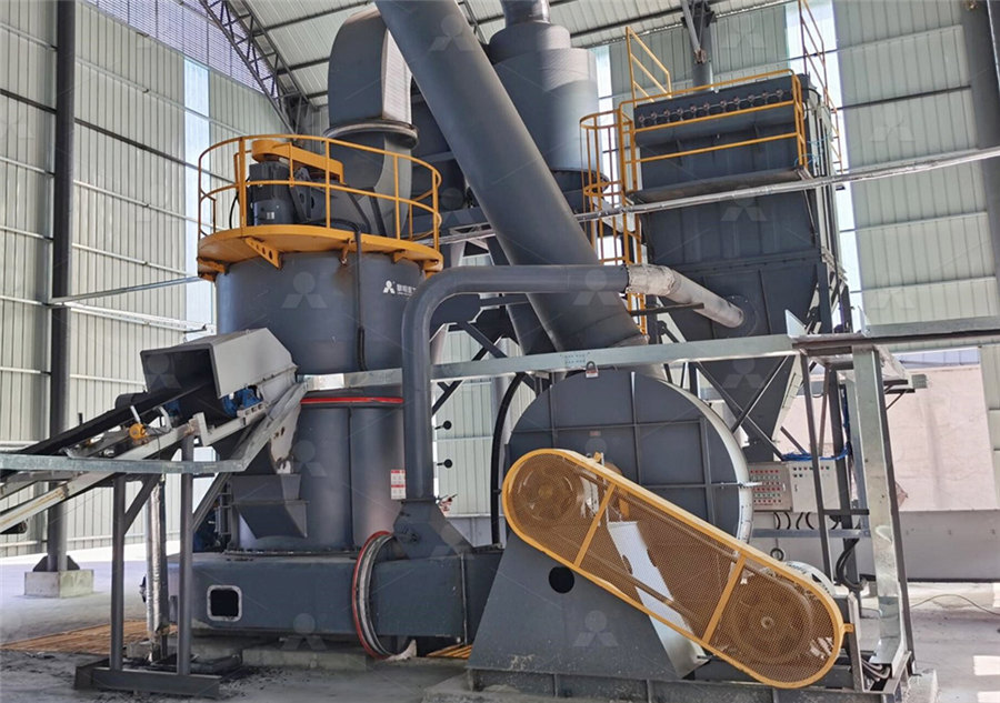
LM Vertical Roller Mill
Input size:38-65mm
Capacity: 13-70t/h
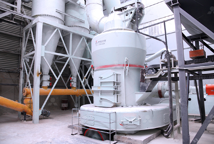
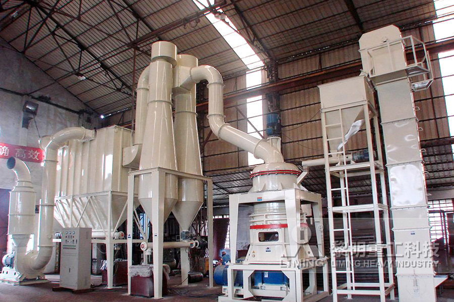
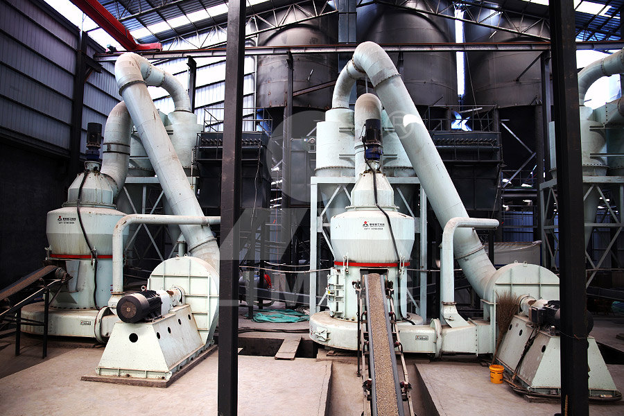
Raymond Mill
Input size:20-30mm
Capacity: 0.8-9.5t/h
Sand powder vertical mill
Input size:30-55mm
Capacity: 30-900t/h
LUM series superfine vertical roller grinding mill
Input size:10-20mm
Capacity: 5-18t/h
MW Micro Powder Mill
Input size:≤20mm
Capacity: 0.5-12t/h

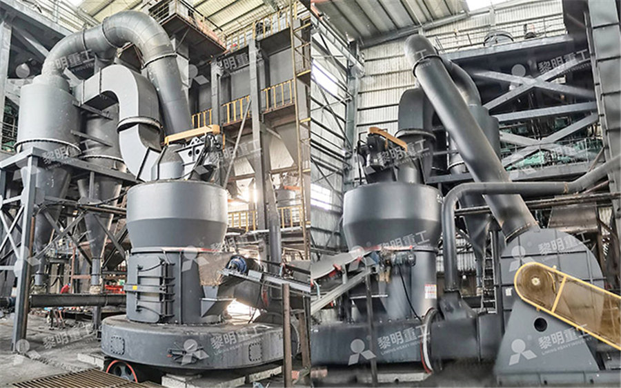
LM Vertical Slag Mill
Input size:38-65mm
Capacity: 7-100t/h
LM Vertical Coal Mill
Input size:≤50mm
Capacity: 5-100t/h
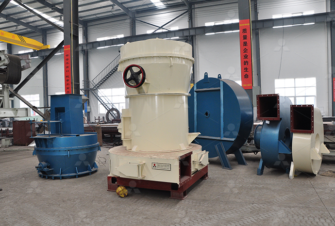
TGM Trapezium Mill
Input size:25-40mm
Capacity: 3-36t/h

MB5X Pendulum Roller Grinding Mill
Input size:25-55mm
Capacity: 4-100t/h
Straight-Through Centrifugal Mill
Input size:30-40mm
Capacity: 15-45t/h
36 slot 2stage reducer lucky group diagram
Sketch of the twostage reducer Download Scientific Diagram
Download scientific diagram Sketch of the twostage reducer from publication: Automated optimal design of a twostage helical gear reducer The design space of multistageDownload scientific diagram Sketch of the twostage reducer from publication: 登录2024年9月8日 The twostage reducer gearbox designed in SolidWorks features a robust system utilizing only spur gears for speed reduction and torque increase The design includes two 2 stage reducer gear box GrabCADABSTRACT Gearbox designed is safe affordable of performance efficient with respective speed and torque required to clear the dynamic event satisfactorily It is 2 stage reduction gearbox Design and Analysis of Two Stage Reduction Gearbox IRJET
.jpg)
Automated optimal design of a twostage helical gear reducer
In this paper a Genetic Algorithm (GA) was used for obtaining optimal models for partial gear ratios in order to achieve a 3 stage helical speed reducer with minimum mass or length The The two stage reduction gearbox consists of three shafts and four gears (two driver gears, two driven gears) The driver gear of the first stage of reduction which is probably the smallest DESIGN AND ANALYSIS OF A TWO STAGE REDUCTION GEARBOXIn this paper an optimal design of twostage speed reducer is presented The novelty of this work consists in the complex and complete approach of the optimal design of gearings The chosen Optimal design of twostage speed reducer AcademiaThe newly designed twostage cycloidal speed reducer, presented in this paper, has one cycloid disc for each stage, that is, two cycloid discs in total, which means that it is rather compact A New Design of a TwoStage Cycloidal Speed Reducer
Determining Optimal Gear Ratios of a Twostage Helical Reducer
This article introduces a study on the optimal calculation of gear ratios of a twostage helical reducer In the study, the acreage of the cross section of the reducer was chosen as the Here we tackle a twostage helical gear transmis process (sizing of shafts, further stages, bearings, houssion design problem (complete with the sizing and selection ing, etc) to Automated optimal design of a twostage helical gear reducer2024年8月14日 A 2stage reduction gearbox is a mechanical device used to decrease the speed of an input shaft and increase torque in two stages This type of gearbox is often used in 2 Stage Reduction GearBox GrabCADDownload scientific diagram Winding setup for a 36slot, 4pole, squirrelcage induction motor: (top) winding diagram; (bottom) winding connections from publication: Generalized MMF space Winding setup for a 36slot, 4pole, squirrelcage
Types and Mechanisms of Gear Reducers KHK
Generally, reduction ratio is limited to 1:6 for one stage Table 22 shows the gears for bevel gear reducers Types and mechanisms of gear reducers with skew axes Figure 24 Structure of TRIRED reducer Figure 24 Structure of 36 slot three phase 4 pole motor rewindinghow to make diagram3 phase motor winding diagram 36 slot 6 pole winding36 slot 4pole 3 phase winding diagram36 sl36 slot three phase 4 pole motor rewindinghow to make diagram 2018年9月23日 PDF Traditional cycloidal speed reducers (with two cycloid discs per one stage, mutually turned by an angle of 180°) are well known for their Find, read and cite all the research you need (PDF) Dynamic Behavior of a TwoStage Cycloidal Speed Reducer of 2011年8月1日 The newly designed twostage cycloidal speed reducer, presented in this paper, has one cycloid disc for each stage, that is, two cycloid discs in total, which means that it is rather compactA New Design of a TwoStage Cycloidal Speed Reducer

Structure of twograde spur gear reducer Download Scientific Diagram
Download scientific diagram Structure of twograde spur gear reducer from publication: Multiobjective optimization design of spur gear based on NSGAII and decision making Optimization Download scientific diagram Schematic of 36slot 4pole stator winding (generated with the BobiSoft Software [21]): (left) threetier concentric winding; (right) doublelayer imbricated winding Schematic of 36slot 4pole stator winding (generated2019年9月12日 The singlestage reducer consists of a gear or a worm gear transmission The latter unit is used to transmit the prime mover power to the working machine and to operate the working machine at the required speed The twostage reducer is also called a twostage worm gear reducer It is divided into a twostage cast iron worm gear reducer and a twostage RV The difference between single stage and two stage gearboxThe SinglePhase Induction Motor (SPIM) has gained widespread adoption in various power applications This article introduces a new study and analysis of SPIM, focusing on its highfrequency (HF Conventional windings design in the 24 slots of the single
.jpg)
3 Phase 36 Slots 2 Pole Double Layer Winding Design ll YouTube
3 Phase 36 slots 2 Pole double Layer Winding diagram*****How to draw 3 phase 36 slots double La2024年9月22日 36 SLOT COOLER MOTOR WINDING DETAIL Cooler motor mostly comes in 24 and 36 slots, the 24 Slot motor that we have can be REWIND in 3 speed and the 36 slots can be Rewinding with little comfort because the 36 Slot Cooler Connection Diagram Motor Coil 2010年3月28日 Running the algorithm described earlier yielded a reducer with a 28×27 division of the transmission ratio and axial distances of 80 and 100 mm on stages one and two respectively, weighing 443 kg This solution was found on the boundary of the second transmission stage Hertzian contact pressure constraint, very near to four additional constraint Automated optimal design of a twostage helical gear reducer 2024年8月14日 A 2stage reduction gearbox is a mechanical device used to decrease the speed of an input shaft and increase torque in two stages This type of gearbox is often used in applications where significant torque is required at a lower speed, such as in industrial machinery, automotive transmissions, or robotics2 Stage Reduction GearBox GrabCAD
The Highpayload Manipulator Development Based on Novel Twostage
2020年7月1日 A disassembled twostage cycloidal speed reducer for hub motor A reducer for the hub motor is designed in Figure 2 The expression for the speed reducer ratio í µí± is í µí± = (í µí± 2021年11月27日 If that is the case, then consider yourself lucky because in this article you will find all the information you need to know about the EZGo Txt 36 Volt Wiring Diagram EZGo Txt 36 Volt is a golf cart made by a company called EZGo This golf cart runs on 36 volts of electricity and it has a unique wiring systemEzgo Txt 36 Volt Wiring Diagram Wiring Draw And Schematic2018年1月28日 36 slot motor 2 pole rewinding motor rewinding data how to make diagram36 slot motor 2 pole rewinding motor rewinding data how to make diagram2019年2月5日 With single reduction ratios up to 121:1, we can offer single stage reducers where others must move to two or three stages This allows for a compact offering, Ltd and its group companies Call Us: 18886354780; Us: [ protected] US Headquarters Address 4200 Holland Blvd Chesapeake, VA 23323; Trade Controls;Cyclo® 6000 Speed Reducer Sumitomo Gearmotors Reducers
.jpg)
Design of a PlanetaryCycloDrive Speed Reducer Cycloid Stage,
The RV is a 2stage speed reducer which includes: a spur gear stage with involute teeth and an epicyclic gear reduction stage The first stage has an input gear (sun gear) coupled with in this case three satellite gears They are connected to the crankshafts via splines The first stage can be modified to change the overall unit ratio2022年4月10日 2 hp 3 Phase Motor Winding 36 Slot 1400 Rpm Motor Winding Data Motor Winding + Connection Diagram #motorwinding #repairing #winding #connection #motorconn2 hp 3 Phase Motor Winding 36 Slot 1400 Rpm Motor Winding Download scientific diagram The singlestage cycloidal speed reducer from publication: Numerical and experimental analysis of the cycloid disc stress state The paper deals with the stress The singlestage cycloidal speed reducer Download Scientific DiagramIn many robotic applications, the joint is required to have a small volume, low weight and high torque output In this paper, based on the finite element analysis (FEA), a 36slot 40pole outer Structural diagram of the lever reducer (a) Fixedaxis

2 stage reducer gear box GrabCAD
2024年9月8日 The GrabCAD Library offers millions of free CAD designs, CAD files, and 3D models Join the GrabCAD Community today to gain access and download!Download scientific diagram 3D model of the investigated singlestage cycloidal speed reducer from publication: Numerical and experimental analysis of the cycloid disc stress state The paper 3D model of the investigated singlestage cycloidal speed reducer2019年6月12日 Designing compact multistage speed reducers are challenging demands of nowadays mechanical power transmission manufacturer 50436 18 16 15 71 63 47 80 125 160 0025900697 051 625 19 (PDF) 3 STAGE HELICAL SPEED REDUCER PARTIAL GEAR RATIOS 2014年9月1日 As shown in Fig 1, the conventional onestage gear reducer mainly consists of the case (1) (as fixed frame), crank (2), cycloidal disc (3) and output disc (4)When operating, the input crank deflects the cycloidal disc such that the cycloidal disc orbits and wobbles about the center of the crank shaft because of the crank's eccentricity and meshing between the disc Design of a twostage cycloidal gear reducer with tooth
Determining Optimal Gear Ratios of a Twostage Helical Reducer
Determining Optimal Gear Ratios of a Twostage Helical Reducer for Getting Minimal Acreage of Cross Section Nguyen Khac Tuan1, Vu Ngoc Pi2, Nguyen Thi Hong Cam2, Tran Thi Phuong Thao2, Ho Ky Thanh2, Le Xuan Hung2, Hoang Thi Tham3 1Automotive and Power Machinery Faculty, Thai Nguyen University of Technology, Thai Nguyen 23000, Vietnam 2Mechanical Download scientific diagram Basic repeating unit of 36slot/42pole, 6kW SPM machine consisting of six stator slots and seven poles from publication: Analysis of Surface Permanent Magnet Basic repeating unit of 36slot/42pole, 6kW SPM ResearchGate2022年1月2日 Each stator slot is covered twice in the above 3phase (R, Y, and B) machine design Design of Armature Winding for 72 Stator Slots, 3Phase, 50H z, 8 Poles Induction Motor For design of each electrical machine’s armature winding, we must first compute the slots per pole, then the slots per pole per phase and finally, the electrical angle between the windings of Design of Armature Winding for 24,36,72 Stator Slots a2z2018年5月7日 In This Video I Showed Motor Rewinding 36 Slots 3 Phase 6 Pole With Diagram Here I Described andCalculate All Data If You New And Want To Learn Induction MInduction Motor Rewinding 36 Slots 3 Phase 6 Pole With Diagram
.jpg)
Threedimensional model of the twostage reducer
Download scientific diagram Threedimensional model of the twostage reducer from publication: 3Dbased multiobjective cooperative disassembly sequence planning method for remanufacturing Briggs and Stratton 008301 Gear Reducer, Oil Group Exploded View parts lookup by model Briggs and Stratton 008301 Gear Reducer, Oil Group Parts Diagram SWIPE SWIPE Air Cleaner, Muffler; Alternator, Controls, Governor Spring, Ignition; Blower Housing/Shrouds, Flywheel Groups;Briggs and Stratton 008301 Gear Reducer, Oil Group Parts Diagram2018年1月1日 Gear ratios versus total reducer ratio From the results of the program, the following regression model were proposed in order to determine the gear ratio of the first stage: 0667 1 09365 t uuDetermining Optimal Gear Ratios of a Twostage 2008年11月7日 In this paper an optimal design of twostage speed reducer is presented The novelty of this article consists in the complex and complete approach of the optimal design of gearingsOptimal design of twostage speed reducer ResearchGate

CAT Question Paper 2021 DILR Slot 2, 2IIM CAT CAT 2024 CAT
Detailed Vedio and text Solutions for CAT 2021 DILR Slot 2 2IIM CAT Question Bank; Online CAT Incorrect: 3681% Unattempted: 5526% CAT 2021 Slot 2 DI LR Object o4 was given to Disha; Barat; Charles; In the group stage of the game, Download scientific diagram Exploded view of the overall structure of the reducer from publication: (FEA), a 36slot 40pole outer rotor surfacemounted permanent magnet Exploded view of the overall structure of the reducerDownload scientific diagram Four typical stator configurations (a) 12 stator slots (b) 24 stator slots (c) 36 stator slots (d) 36 open stator slots from publication: Development of a Four typical stator configurations (a) 12 stator slots (b) 24 Download scientific diagram Twostage gear reducer from publication: New analysis tools for the diagnosis of gear systems In order to cope with constraints of the industrial world, the early Twostage gear reducer Download Scientific Diagram
Single Stage Gear Reducer Project
This system makes use of gears with a motor to achieve the desired functionality Gear reducers are widely used in gearboxes One more use of gear reducers is in gear switching in automobiles This system demonstrates the single stage gear reducer assembly using motorize shafts and gear mechanisms in a gearbox framewhere: vi1, vi2 are the components of the volumes corresponding to the helical gears; ρ is the density of steel (ie 785106 mm3/kg); d a1 and da6 are the outside diameters of the helical gears 1 and 6 (see Fig2); aw{1}, aw{2} and aw{3} are the standardized center distances Fig 2 – The helical gearings of a 3 stage speedreducer 433 STAGE HELICAL SPEED REDUCER PARTIAL GEAR RATIOS