


MTW European Type Trapezium Mill
Input size:30-50mm
Capacity: 3-50t/h
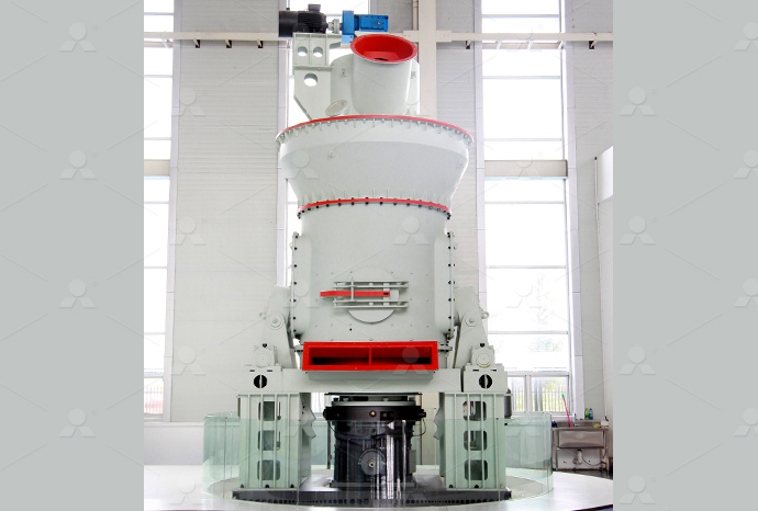
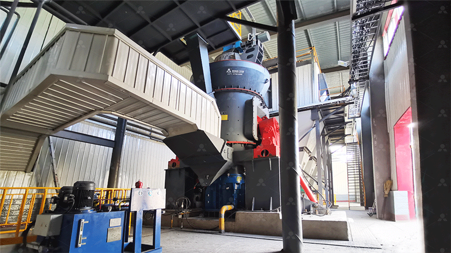
LM Vertical Roller Mill
Input size:38-65mm
Capacity: 13-70t/h
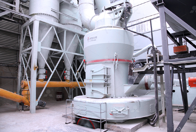
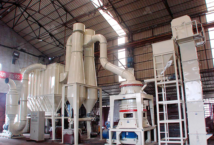
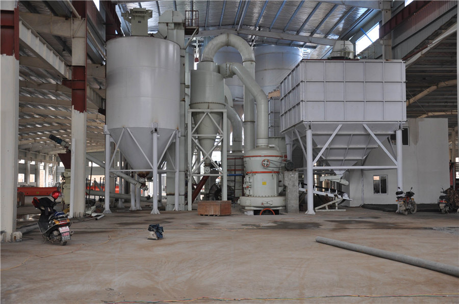
Raymond Mill
Input size:20-30mm
Capacity: 0.8-9.5t/h
Sand powder vertical mill
Input size:30-55mm
Capacity: 30-900t/h
LUM series superfine vertical roller grinding mill
Input size:10-20mm
Capacity: 5-18t/h
MW Micro Powder Mill
Input size:≤20mm
Capacity: 0.5-12t/h

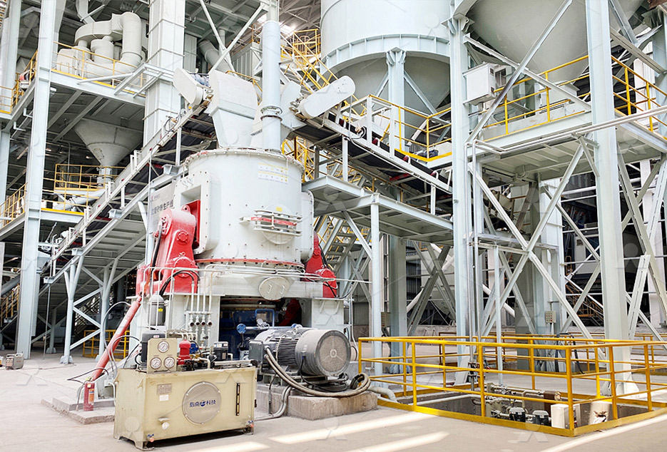
LM Vertical Slag Mill
Input size:38-65mm
Capacity: 7-100t/h
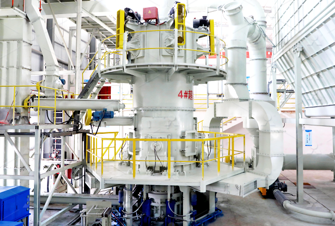
LM Vertical Coal Mill
Input size:≤50mm
Capacity: 5-100t/h
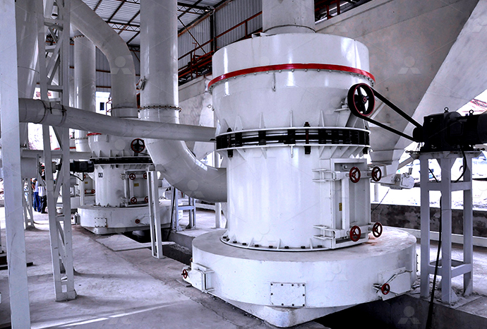
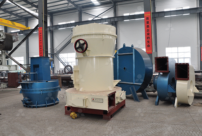
TGM Trapezium Mill
Input size:25-40mm
Capacity: 3-36t/h

MB5X Pendulum Roller Grinding Mill
Input size:25-55mm
Capacity: 4-100t/h
Straight-Through Centrifugal Mill
Input size:30-40mm
Capacity: 15-45t/h
Fluidized bed air flow mill schematic diagram
Schematic representations of fluidized beds in different regimes
The behavior of gas and solid in bed was influenced by the upward air flow which was captured using digital camera to identify the flow pattern in the riser The fluidization image from theThe behavior of gas and solid in bed was influenced by the upward air flow which 登录Proper fluidization is obtained by distributing the feed over the bed surface and designing the fluid bed to allow total mixing (backmix flow) within its confines The product temperature and Dairy Process Engineering: Lesson 19 BATCH FLUIDIZATION, nozzle is installed in the fluid bed system container in combination with a flow bed that directs the air flow The nozzle sprays liquid into the fluidized product bed from underneath the bed, FLUIDIZED BED SYSTEMS WSG Glatt
.jpg)
Thermal Processing Equipment Fluidized Bed Systems
bed can be delivered with or without submerged heat exchangers Figure 10 indicates the range of usage of both types of fluid beds In this diagram pressure drop on product against fluidizing 2012年9月1日 Flow regime diagram for fluidized beds The fluidization state is bounded between a packed bed for overly low gas velocities and pneumatic conveying for overly high gas Generalized flow regime diagram of fluidized beds based on the A schematic diagram for the steps from the beginning to the end of the fluidizedbed is shown in Figure 1 The mixture that enters the fluidized bed is divided into nine parts and thenSchematic diagram of the fluidized bed ResearchGate2011年1月17日 This paper presents a three dimensional Computational Fluid Dynamics (CFD) model to investigate the flow dynamics of solid–gas phases during fine grinding in an air jet CFD simulation and experimental analysis of flow dynamics and
.jpg)
INTRODUCTION TO FLUIDIZED BEDS Washington University in
on fluidization behavior and prepared a flow regime diagram The flow regime diagram was further modified by Kunii and Levenspiel (1997) For given particles and operating velocity, the gas performance air classifier, fluidised bed opposed jet mills achieve extremely fine particle sizes – regardless of the hardness: even diamonds with a value of 10 on the Mohs' scale can be ALPINE fLuIdIsEd bEd oPPosEd jEt mILLSchematic diagram of the experimental setup The grinding of material in the fluidized bed opposed jet mill is primarily due to abrasion of the grains During the grinding the fine particles RESEARCH AND MODELING OF PROCESSES IN THE FLUIDIZED 2022年9月1日 The first fluidized bed gasifier was commercialized in 1926 A schematic diagram of his process is shown in Fig 2 A stirring rod was added near the distributor to remove the ash Air was delivered too near the top of the bed A bulbous expansion defined the freeboard to minimize the loss of the fines with the product gases100 years of scaling up fluidized bed and circulating fluidized bed
.jpg)
CFD simulation and experimental analysis of flow
The compressible and turbulent gas–solid multiphase flow inside a fluidized bed opposed jet mill was systematically investigated through numerical simulations using the Euler–Euler approach along with the kinetic theory of Croquis y Schematic diagram of the fluidized bed dryer: (1) blower, (2) pitot tube, (3) a drying chamber, measuring devices for air pressure drop, air flow rate, inlet air tempera ture, Schematic diagram of the fluidized bed dryer: (1) Download scientific diagram Schematic diagram of a fluidizedbed dryer with recycle pipe from publication: Drying Strategies for FluidizedBed Drying of Paddy The main objective of this work Schematic diagram of a fluidizedbed dryer with recycle pipeH bed is the bed height (m) and ρ g is the gas density (kg/m 3 ) The minimum bed height used in the Nilsson’s experiments is 005 m, thus there is a (H bed − 005) term in the above equationSchematic Diagram of the Laboratory Scale Plug Flow Fluidized Bed
.jpg)
Schematic representation of fluidized bed coating process
Download scientific diagram Schematic representation of fluidized bed coating process from publication: Development and Application of a Process Window for Achieving HighQuality Coating in a 2023年12月1日 Fig 1 (A) depicts a schematic diagram of the experimental setup employed in this study The setup comprises a fluidized bed column with an inner diameter of 32 mm and a height of 15 m The column is made of highpurity corundum and is embedded in an electrically heated furnaceFlow regimes and transitions in an ultrahigh temperature gas The difficulty of distributing gas evenly into the fluidized bed has encouraged innovation in the distributor design Some researchers used a rotary air distributor to improve the bubble Schematic diagram of the experimental fluidized bedDownload scientific diagram Fluidized bed apparatus: a photograph, b schematic from publication: Effect of air intake temperature on drying time of unhulled rice using a fluidized bed dryer Fluidized bed apparatus: a photograph, b schematic
Flow diagram of a wellmixed fluidized bed dryer Air flow
Flow diagram of a wellmixed fluidized bed dryer Air flow regime in the fluidized drying technology has a crucial role in the drying process The terminal velocity of different grains is different2024年2月5日 This is a schematic diagram illustrating the dry granulation process Image source: NIH The air moving upwards at high velocity blows the particles apart within the bed resulting in an “expanded bed” As the air flow A Definitive Guide to Fluid Bed Granulation Process 2011年2月1日 As a result, an extension of the boundary between the fluidized bed and pneumatic conveying, ε → 1 and n = 1, for small particles for heterogenous fluidization is drawnFlow regime diagram for vertical pneumatic conveying and fluidized bed Schematic diagram of the circulating fluidized bed (1) Air reactor, (2) fuel reactor, (3) cyclone for particle separation, (4) and (5) loop seals fluidized with steamSchematic diagram of the circulating fluidized bed
.jpg)
FLUIDIZED BED SYSTEMS WSG Glatt
FLUIDIZED BED SYSTEMS WSG PRO GPCG 10 GPCG PRO 2 3 Glatt Integrated Process Solutions THE WORLD OF FLUID BED Top technology in the production of combination with a flow bed that directs the air flow The nozzle sprays liquid into the fluidized product bed from underneath the bed, distributing the sprayed liquid over the2023年2月15日 Fig 4 shows the schematic diagram of the initial bed filling of the physical and model fluidized bed used in the highspeed photographic experiment and DEM numerical simulation Inside the fluidized bed, mixed particles of 5 mm and 30 mm in diameter were placed with a mixing ratio of 3:7, both with a particle density of 2500 kg/m 3 and an initial bed Gas–solid flow characteristics of fluidized bed with binary particlesby the fluidized bed under the pressure of 02 MPa Fig 3 Microstructure diagram of Silicon Carbide powder W 14 by the fluidized bed under the pressure of 05 MPa and 03 MPa 23 Controlling granule morphology The fluidizedbed jet mill (LNC3400) was chosen as the experimental equipment in this paper The mechanism and structure are shown FLUIDIZEDBED JET MILL FOR CONTROLLING GRANULE MORPHOLOGY OF ULTRA Fig 1 shows a schematic diagram of the fluidized bed reactor system for biomass fast pyrolysis It was mainly consisted of gassupplying unit, gas preheater, fluidized bed reactor, Process schematic for Circulating fluidized bed
.jpg)
2 Schematic diagram of a fluidized bed dryer
Download scientific diagram 2 Schematic diagram of a fluidized bed dryer from publication: Atmospheric Freeze Drying Vacuum freeze drying has been the benchmark technology for making high Download scientific diagram Schematic diagram of experimental setup For fluidized bed drying, the most significant component is the drying column Therefore, the thermal balance was derived by Schematic diagram of experimental setup For fluidized bed Progress in dynamic simulation of thermal power plants Falah Alobaid, Bernd Epple, in Progress in Energy and Combustion Science, 2017 2352 Fluidized bed The fluidized bed is a bulk of solid particles located in a vertical vessel and the gas or liquid flows from the bottom via a porous plate or nozzles The gassolid fluidized bed is characterised by several advantages Fluidized Bed an overview ScienceDirect Topics2024年1月20日 This air flow causes the particles to become floating, resembling a fluid, hence the term “fluidized” As a result, each particle is surrounded by Fluidized Bed Dryer (FBD) Pros and Cons, Fluidized Bed Dryer Diagram, Fluidized Bed Dryer (FBD): The Ultimate Guide for
.jpg)
Eulerian Multiphase Simulation of the Particle
2020年12月9日 The compressible and turbulent gas–solid multiphase flow inside a fluidized bed opposed jet mill was systematically investigated through numerical simulations using the Euler–Euler approach along with the kinetic 2019年9月7日 Fluidized bed dryer (fluidized bed dryer) achieves faster drying rates with the drying time ranging from 20 minutes to 40 minutes With the material in a fluidized state, there are no hot spots It enhances the product’s Fluidized Bed Dryer : Parts, Working Principle and Download scientific diagram Schematic of circulating fluidized bed combustion (CFBC) unit 29 from publication: Fluidized Bed Combustion (FBC) Fly Ash and Its Performance in Concrete Concerns Schematic of circulating fluidized bed combustion (CFBC) unit 29The reports cover combustion in a circulating fluidized bed [9,10], bubbling fluid bed unit [11], or using the grate furnaces in stokerfired boilers technique [12,13]Schematic diagram of the fluidized bed system
Schematic diagram of the fluidized bed combustor
Download scientific diagram Schematic diagram of the fluidized bed combustor from publication: 38 mm, and 63 mm wood particles under air flow velocity of 012 ms⁻¹Download scientific diagram Scheme of the fluidized bed opposed gas jet mill considered in the numerical studies from publication: Eulerian Multiphase Simulation of the Particle Dynamics in a Scheme of the fluidized bed opposed gas jet mill considered in 2007年1月1日 Fixed, Fluidized, and Mobilized beds (9) The fixed bed (a) occurs when the approach velocity or superficial velocity, ( Vo ) , is much smaller than the minimized fluidization velocity,( V mf )(PDF) Fluidized Bed Systems: A Review ResearchGateDownload scientific diagram Schematic of a circulating fluidized bed boiler from publication: CFD ANALYSIS OF MULTIPHASE TRANSIENT FLOW IN A CFB RISER Modeling the various flow characteristics Schematic of a circulating fluidized bed boiler
.jpg)
Schematic diagram of an internally circulating fluidized bed
Download scientific diagram Schematic diagram of an internally circulating fluidized bed combustor/incinerator from publication: Combustion Characteristics of Spent Catalyst and Paper Sludge Figure 1 shows the schematic diagram of a closedfluidized bed dryer used in this study The fluidized bed consisted of a cylindrical chamber (210 mm in diameter and 150 cm in height), 5 kW hotair Schematic diagram of fluidized bed dryer setup2020年12月27日 A fluid bed dryer diagram, dryer works on the principle of fluidization of the materials In the fluidization process, hot air or gas flow is introduced through the bed of solid particulates This gas or air will move Fluid Bed Dryer Diagram RAVI INTERNATIONAL Schematic diagram of the FJM200 fluidized bed opposed jet mill 1, Infeed; 2, collection; 3, classification section; 4, grinding section; 5, compressed air; 6 Schematic diagram of the FJM200 fluidized bed opposed jet mill
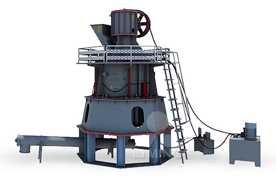
CNY Improved collision type fluidised bed airflow mill
The utility model relates to an improved collision type fluidized bed airflow mill whose mill cavity comprises a sorting area I, a transmission area II and a disintegrating area III from top to bottom The utility model is characterized in that the length of the transmission area II are obviously increased, and the length L/ the diameter D of the transmission area achieves 3 to 10Download scientific diagram Schematic diagram of fluidized bed gasification technology taken from [30] from publication: Thermochemical processes for biofuels production from biomass The Schematic diagram of fluidized bed gasification technology Download scientific diagram Schematic diagram of the bubbling fluidized bed reactor from publication: labscale bubbling fluidizedbed (BFB) reactor with a feed capacity of 35 kg/h, Schematic diagram of the bubbling fluidized bed reactorDownload scientific diagram Schematic of a typical bubbling fluidized bed incinerator (fluidized bed sludge combustor of Brugge, Belgium, reprinted with permission from [7], Schematic of a typical bubbling fluidized bed incinerator (fluidized
Flow through Packed Beds and Fluidized Beds Clarkson
A fluidized bed is a packed bed through which fluid flows at such a high velocity that the bed is loosened and the particlefluid mixture behaves as though it is a fluid Thus, when a bed of particles is fluidized, the entire bed can be transported like a fluid, if desired Both gas and liquid flows can be used to fluidize a bed of particlesDownload scientific diagram Schematic of the sunflower meal is ground by a hammer mill after which air zigzag The innovation of employing the pulsing airflow to the fluidized bed Schematic of the active pulsing air classifier (1) Air blast; (2) flow 2016年12月31日 PDF The circulating fluidized bed boiler (CFB boiler) is the secondgeneration fluidized bed boiler, A schematic diagram of the structure of a CFB boiler is shown in Fig 41(PDF) Heat Transfer in Fluidized Beds ResearchGate