


MTW European Type Trapezium Mill
Input size:30-50mm
Capacity: 3-50t/h
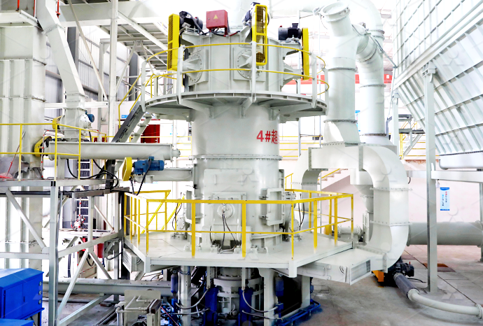
LM Vertical Roller Mill
Input size:38-65mm
Capacity: 13-70t/h
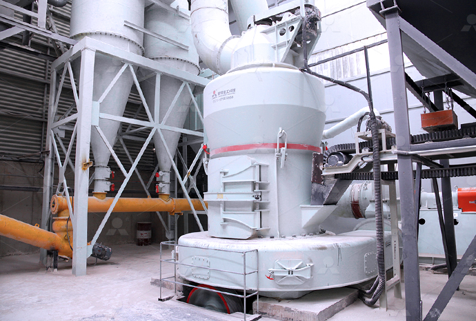
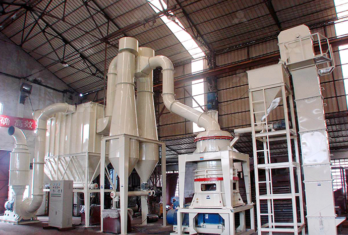
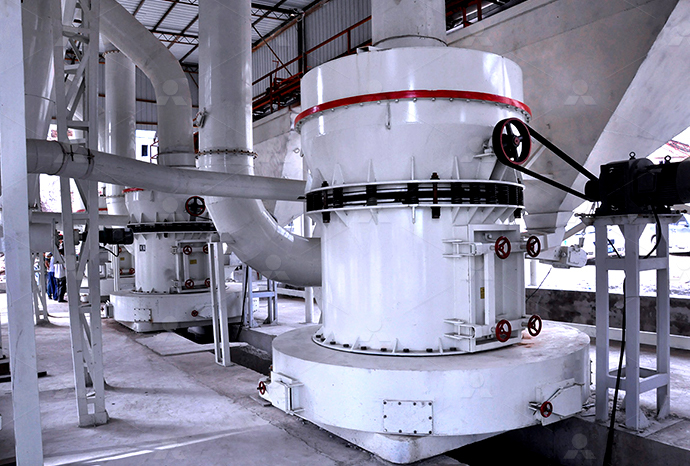
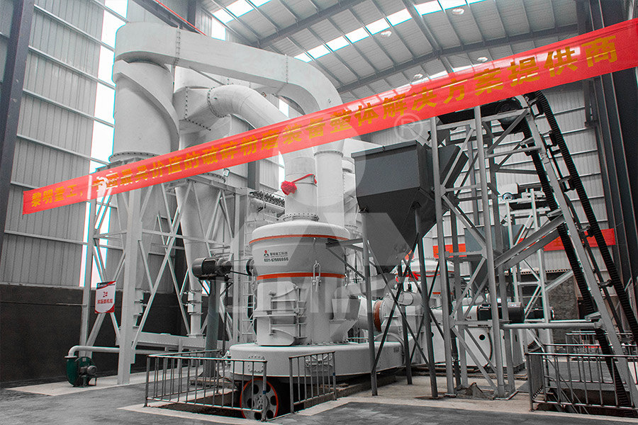
Raymond Mill
Input size:20-30mm
Capacity: 0.8-9.5t/h

Sand powder vertical mill
Input size:30-55mm
Capacity: 30-900t/h
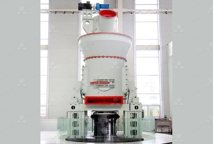
LUM series superfine vertical roller grinding mill
Input size:10-20mm
Capacity: 5-18t/h
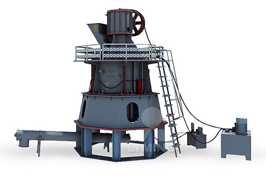
MW Micro Powder Mill
Input size:≤20mm
Capacity: 0.5-12t/h

LM Vertical Slag Mill
Input size:38-65mm
Capacity: 7-100t/h

LM Vertical Coal Mill
Input size:≤50mm
Capacity: 5-100t/h
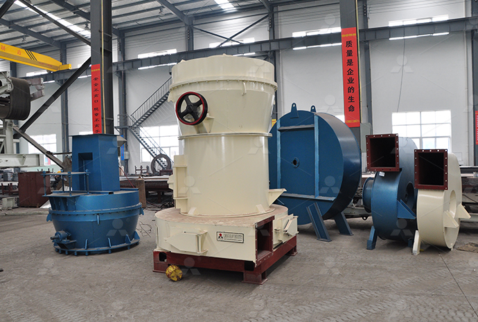
TGM Trapezium Mill
Input size:25-40mm
Capacity: 3-36t/h

MB5X Pendulum Roller Grinding Mill
Input size:25-55mm
Capacity: 4-100t/h
Straight-Through Centrifugal Mill
Input size:30-40mm
Capacity: 15-45t/h
Electrical schematic diagram of electrohydraulic plow feeder

Electrical Kit Installation Instructions Fisher Engineering
Read this manual and labels on the snowplow before installing or operating the snowplow ✪ WARNING Indicates a potentially hazardous situation that, if not avoided, 展开We urge all mechanics to read this manual carefully before attempting to service the WESTERN snowplow equipment covered by this guide Service of your WESTERN snowplow equipment SNOWPLOWS MECHANIC'S GUIDE Western ProductsIdentify wires for the parking lamp on the driver side and the turn signals on both sides of the vehicle Attach a black selfstripping bullet receptacle connector (found in harness kit) to each CHEVY/GMC 1500/2500/3500 4x4 1999 LATER VEHICLE To ensure years of optimum snowplow performance, review the contents of this manual It contains assembly information, detailed diagrams, complete parts listings, maintenance #1 POWER PLOW MANUAL (200102) Blizzard Plows
INSTALLATION OWNER’S MANUAL SnoWay Intl
Most importantly, this manual provides an operating plan for safe use Refer to the Table of Contents for an outline of this manual Please keep this manual with your machine at all times Read this manual before operating or servicing snowplow This manual has been prepared to acquaint you with the safety information, operation and maintenance of your new FISHER® Solenoid Electric Hydraulic Pak Owner's Manual Fisher EngineeringHYDRAULIC SAFETY • Always inspect hydraulic components and hoses before using Replace any damaged or worn parts immediately • If you suspect a hose leak, DO NOT use your hand SNOWPLOWS MECHANIC'S GUIDE Fisher EngineeringTwo pushpull CABLES link the cab control to the ISARMATICÕ valves One cable actuates the 3way valve controlling the raiselower movement of the blade The other cable actuates the Westernparts Western Snow Plow Parts Dealer
.jpg)
ELECTRICAL AND HYDRAULIC PARTS SCHEMATIC SnoWay Intl
26R Series 2 Snow Plow; VPlow Flared 29RVHD Series 2 Snow Plow; Flared 29VHD Series 2 Snow Plow; Flared 26V Series 2 Snow Plow; Flared 22V Series 2 Snow Plow; Straight Plows Read and understand labels and the Owner's Manual before installing, operating, or making adjustments Lower the blade when the vehicle is parked Temperature changes could change MG SnowEx RD, HD LT Straight Blade SnowplowsDownload scientific diagram Schematic of a battery powered electro hydraulic forklift with a fixed displacement single direction hydraulic pump and control valves Conventional hydraulic circuit Schematic of a battery powered electro hydraulic Electro Pneumatic control integrates pneumatic and electrical technologies, is more widely used for large applications In Electro Pneumatics, the signal medium is the electrical signal either AC or DC source is used Working medium is compressed air Operating voltages from around 12 V to 220 Volts are often usedLecture 41 ELECTRO PNEUMATIC CONTROL Learning Objectives

Basic Diagrams and Systems Engineering Library
Graphic Symbols for Electrical and Electronic Diagrams (Including Reference Designation Letters) ANSI Y329: Electrical Wiring Symbols for Architectural and Electrical Layout Drawings: ANSI Y32161965: Electrical and Electronic Download scientific diagram Schematic diagram of the electrohydraulic servosystem from publication: An Adaptive Fuzzy DeadZone Compensation Scheme and its Application to ElectroHydraulic Schematic diagram of the electrohydraulic servosystem2020年4月1日 Electrohydraulic control valves are key hydraulic components for industrial applications and aerospace, which controls electrohydraulic motion With the development of automation, digital technology, and communication technology, electrohydraulic control valves are becoming more digital, integrated, and intelligent in order to meet the requirements of Research and Development of Electrohydraulic ControlDownload scientific diagram Schematic of an electrohydraulic servovalve with flappernozzle structure from publication: Cavitation and flow forces in the flappernozzle stage of a hydraulic Schematic of an electrohydraulic servovalve with flapper

Hydraulic Systems Volume 2 ElectroHydraulic Components and
4 Hydraulic Systems Volume 2: ElectroHydraulic Components and Systems Table of Contents 36 ElectroHydraulic Switching Flow Control Valves, 133 Chapter 4: Electrical Circuits for Switching Valves, 134 41 Best Practices for Safe Operation of ElectroHydraulic Systems, 135 42 Basic Electrical Symbols, 140 43 Basic Electrical Devices, 年1月1日 Hydraulic system builders and users will find this book beneficial in understanding the construction and the operating principles of the electrohydraulic systemsHydraulic System Volume 2: ElectroHydraulic Components and Systems2019年8月7日 But why use electro hydraulic diagrams instead of just electrical circuits? The answer lies in the greater control that hydraulic systems offer Through careful manipulation of the flow of hydraulic fluid, it is possible to create precise Electro Hydraulic Circuit Diagrams Wiring Digital and SchematicDownload scientific diagram Schematic diagram of the electrohydraulic system from publication: Parallel Velocity Control of an ElectroHydraulic Actuator With Dual Disturbance Observers In Schematic diagram of the electrohydraulic system
Schematic diagram of the electrohydraulic servo system
Download scientific diagram Schematic diagram of the electrohydraulic servo system from publication: Multiclass fault detection in electrohydraulic servo systems using support vector machines 2022年6月8日 Pilot pressure and electric actuation are the dominant forces in the market and will be for some time Electronic control systems allow for the precise application for pilot actuation (left), where low pressure shifts the The Best Way to Read a Hydraulic SchematicAirbus 380 is a typical more electrical aircraft featured with diverse electrical systems, such as the Local ElectroHydraulic System (LEHS) for the actuation of the landing gearHydraulic diagram of the electrohydraulic servo In operation of electropneumatic controller system, electropneumatic control system is not shown in a single over all circuit diagram, but in two separate diagram one for electrical part and one for pneumatic part Components of electrical signal control Seven electrical devices are commonly used in the controlDesign and Simulation of ElectroPneumatic Sequential System
ELECTRO HYDRAULIC VALVES Moog Inc
ELECTROHYDRAULIC VALVES: A TECHNICAL LOOK 4 This guide contains an opening section on the different valve types currently available from Moog ranging from: • Servo and Proportional valves • Direct and Pilot operated valves • Electrical and Mechanical Feedback valves • Valves with analog and digital electronics • Flow, pressure and axis control valvesDownload scientific diagram Schematic block diagram of the electrohydraulic servosystem from publication: ROBUST OUTPUT FEEDBACK CONTROL OF AN ELECTROHYDRAULIC ACTUATOR WITH UNCERTAIN Schematic block diagram of the electrohydraulic servosystemDownload scientific diagram Schematic diagram of a twostage electrohydraulic servo valve from publication: A seventhorder model for dynamic response of an electrohydraulic servo valve In Schematic diagram of a twostage electrohydraulic servo valveDownload scientific diagram Schematic diagram of the electrohydraulic servosystem [7] from publication: Adaptive Control of the ElectroHydraulic ServoSystem with External Disturbances The Schematic diagram of the electrohydraulic servosystem [7]
Basic level
The following schematic diagram shows the two principal subassemblies in an electrohydraulic system: 13 Design of an electrohydraulic system •signal control section with signal input, signal processing and control energy supply •hydraulic power section with power supply section, power control section and drive sectionNumerous types of speed governors are available but the electrohydraulic type is simple, flexible and gives better performance as far as the regulation of basic parameters is concerned [14][15 Simplified schematic of a hydroelectric power plant2022年6月5日 Traditional construction machinery’s full hydraulic steering system has high energy consumption An electrohydraulic flow matching steering system for electric wheel loaders based on closed ClosedCircuit PumpControlled ElectroHydraulic Download scientific diagram Schematic of hydraulic excavator boom system equipped with an electrical energy recovery system from publication: A Novel Energy Recovery System Integrating Flywheel Schematic of hydraulic excavator boom system

shows schematic diagram of electro hydraulic
Download scientific diagram shows schematic diagram of electro hydraulic system that has been utilized for experiment in [11][20][21][22] The oil stored in the tank feeds the system pump The 2024年6月28日 Introduction In the world of electronics and engineering, the ability to read and interpret schematics is a fundamental skill But what exactly are schematics, and why are they so important? Schematics, or circuit diagrams, are visual representations of electronic circuitsThey use symbols to represent different electronic components and show how these components The Basics of Schematics: Understanding Circuit Diagrams andElectrical electronic symbols and images are used by engineers in circuit diagrams and schematics to show how a circuits components are connected together Circuit layouts and schematic diagrams are a simple and effective way of showing pictorially the electrical connections, components and operation of a particular electrical circuit or systemSchematic Symbols of Electrical and Electronic ComponentsDownload scientific diagram 1: Conventional electrohydraulic circuit of the main lift function of a forklift truck a) Singleacting cylinder, b) proportional valve, c) pressure relief valve, d 1: Conventional electrohydraulic circuit of the main lift
Electro Hydraulic Hybrid Power Steering System SpringerLink
2022年9月24日 In the energy flow of the electro hydraulic hybrid steering system, part of the controller energy is output to the electro hydraulic power assistance module, which is responsible for driving the hydraulic pump to rotate and outputting the highpressure power assistance oil to the rotary valve, so as to drive the piston to move to the corresponding side; The other part is 2019年5月30日 Electrohydrostatic actuator (EHA) replace hydraulic systems with electrical poweronly selfcontained actuators EHAs eliminates the need for separate hydraulic pumps and tubing In most cases, hydraulic electrical actuators include a closed hydraulic system consisting of an electrical drive motor, a pump and a hydraulic cylinder with plunger and actuator stem Basics of Electrohydraulic actuator Instrumentation and 2023年1月19日 Despite the recent related research on the manipulator under an electrohydraulic servo control, researchers mainly focus on the hydraulic highspeed digital servo control technology, 1 highspeed highfrequency valve technology, 2,3 and electrohydraulic servo system optimization algorithm, 4 etc Samakwong 5 used the genetic algorithm (GA) to Research on the electrohydraulic servo system of picking Download scientific diagram Schematic diagram of an Electro Hydraulic Steering system from publication: Unsteady CFD Simulation of a Geared Pump Industrial Utilization, Constraints and Schematic diagram of an Electro Hydraulic Steering system
.jpg)
Schematic diagram of conventional hydraulic excavator
Electrohydrostatic actuator (EHA) is a highly integrated local hydraulic actuation system for more electric aircraft (MEA) However, the motor heating has always been the bottleneck in actual 26R Series 2 Snow Plow; VPlow Flared 29RVHD Series 2 Snow Plow; Flared 29VHD Series 2 Snow Plow; Flared 26V Series 2 Snow Plow; Flared 22V Series 2 Snow Plow; Straight Plows 32 Contractor Series 2 Snow Plow; 29HD Series 2 Snow Plow; 26 Series 2 Snow Plow; 22 Series 2 Snow Plow; 22 DriveWay Series 2 Snow Plow; What Plow Fits? Snow Plow ELECTRICAL AND HYDRAULIC PARTS SCHEMATIC SnoWay IntlDownload scientific diagram Schematic diagram of electrohydraulic servo closedpump control system 1: servo motor; 2: fixed displacement pump; 3/4: oneway valve; 5: accumulator; 6/7: oneway Schematic diagram of electrohydraulic servo closed 2021年2月20日 We are all familiar with the use of a rudder, which helps in turning a ship as and when requiredRudders are the principal system for the entire motion and control of the ships But we mustn’t forget that the entire rudder action is dependent on another pivotal system called the Steering Gear Steering Gear integrated with the rudder system defines the complete ‘turning Understanding Steering Gear in Ships Marine Insight
Schematic diagram of the electrohydraulic servo position system
Download scientific diagram Schematic diagram of the electrohydraulic servo position system from publication: Research on HighPrecision Position Control of ValveControlled Cylinders Based on ElectroHydraulic Proportional Valves Manual Page 3 Chapter 1: Overview Direct Acting vs Pilot Operated The movement of the hydraulic components (such as the spool), inside these valves can be controlled directly by the solenoid actuator Valves which use this type of actuator are know as direct acting valves Another method of controlling ElectroHydraulic Proportional Valvesl installation owner’s manual 22 series snow plows with eis ® plow light harness connections for gravity hydraulics with serial number before 22gINSTALLATION OWNER’S MANUAL SnoWay Intl2019年10月29日 This chapter of hydraulic symbology covers most of what needs to be known to read and create the average hydraulic schematic, since actual electrical symbols are somewhat different Starting with Figure 1, there are three ways to draw an electric operator for solenoid valves, which most people recognizeHydraulic symbology 301: electrical and electronic symbols
Solenoid Isarmatic Hydraulics Wiring Diagram For Western Plow
Service of your WESTERN snowplow equipment is best performed by your local S3) Electrical System – approximate values: Solenoid Valve Coil Resistance = 6 ISARMATIC® HYDRAULIC UNIT PARTS DIAGRAM End Cap Motor MotorFind Western Plow Solenoid on sale right here with the biggest option of Western Plow Solenoid anywhere online Skip to content3 Multiplexed ElectroHydraulic Control System The multiplexed electrohydraulic system allows many subsea control modules (SCMs, discussed in section 4) to be connected to the same communications, electrical, and hydraulic supply lines, which are bundled in the multiplexed electrohydraulic umbilical Therefore, many wells can be controlled viaIntroduction to Subsea Engineering for Electrical Engineers