


MTW European Type Trapezium Mill
Input size:30-50mm
Capacity: 3-50t/h
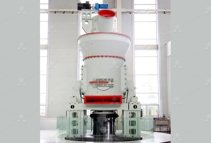
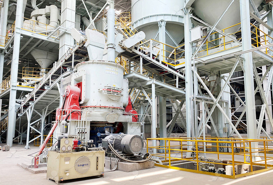
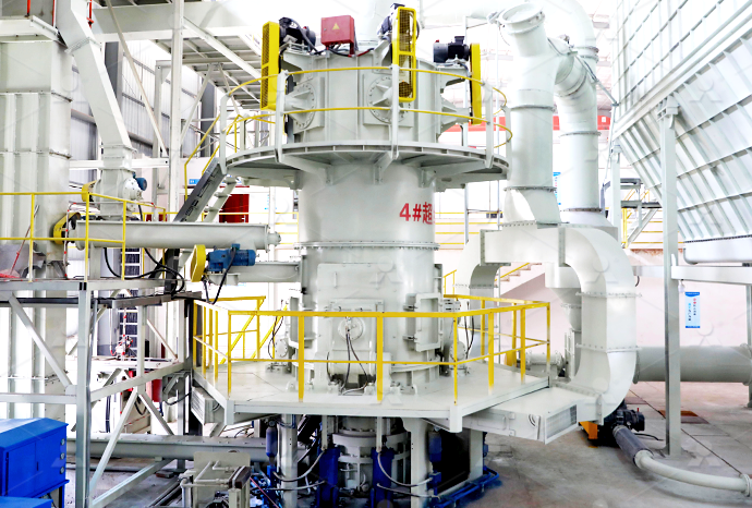
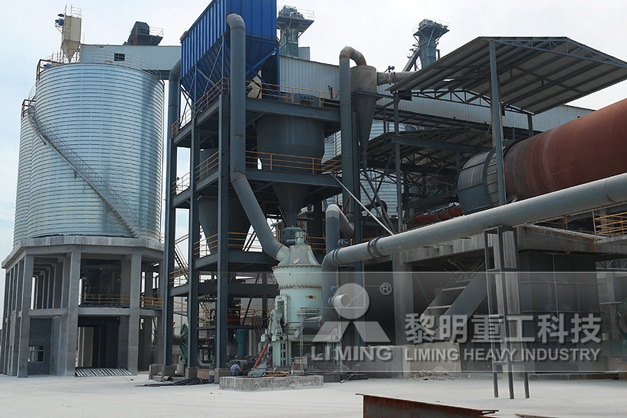
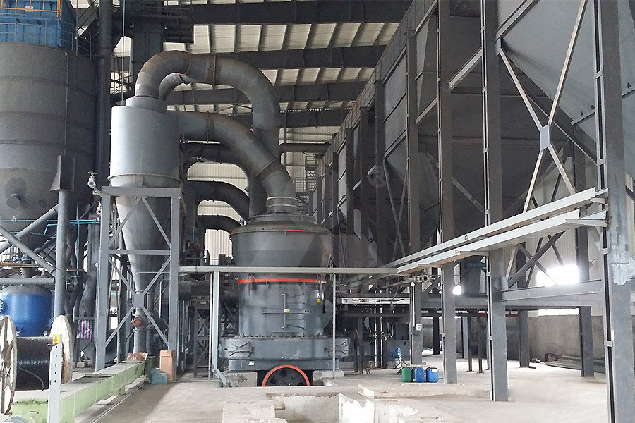
LM Vertical Roller Mill
Input size:38-65mm
Capacity: 13-70t/h
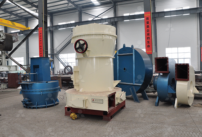
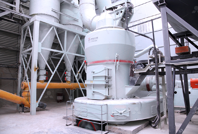
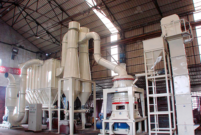
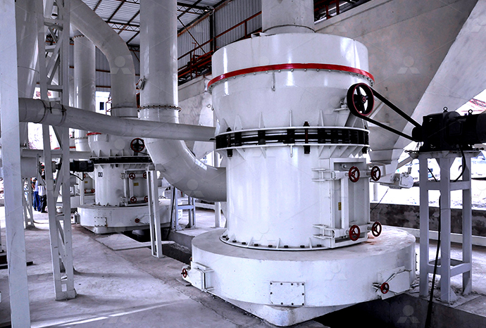
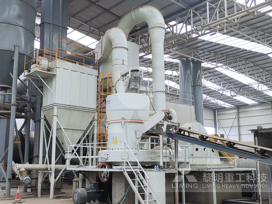
Raymond Mill
Input size:20-30mm
Capacity: 0.8-9.5t/h
Sand powder vertical mill
Input size:30-55mm
Capacity: 30-900t/h
LUM series superfine vertical roller grinding mill
Input size:10-20mm
Capacity: 5-18t/h
MW Micro Powder Mill
Input size:≤20mm
Capacity: 0.5-12t/h
LM Vertical Slag Mill
Input size:38-65mm
Capacity: 7-100t/h
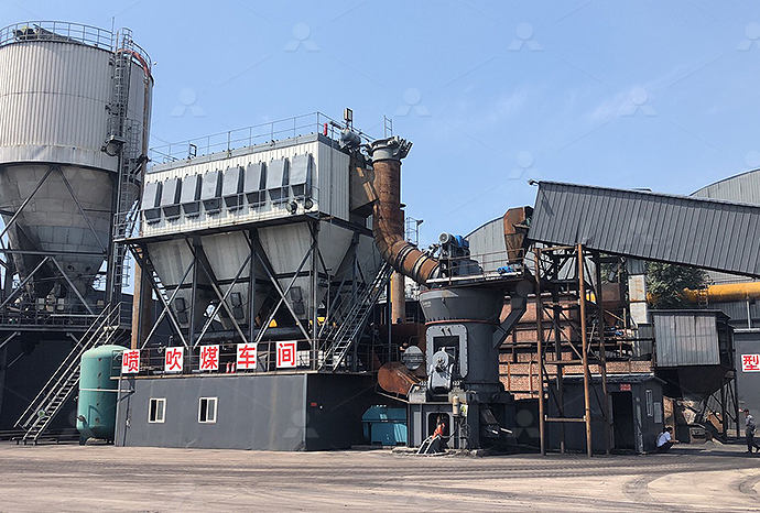
LM Vertical Coal Mill
Input size:≤50mm
Capacity: 5-100t/h
TGM Trapezium Mill
Input size:25-40mm
Capacity: 3-36t/h

MB5X Pendulum Roller Grinding Mill
Input size:25-55mm
Capacity: 4-100t/h
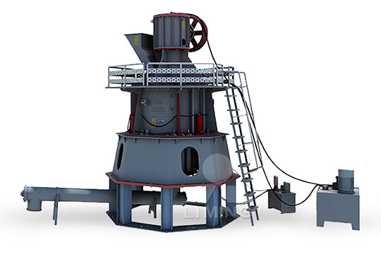
Straight-Through Centrifugal Mill
Input size:30-40mm
Capacity: 15-45t/h
Fourbar mechanism ore mill principle
FourBar Mechanism an overview ScienceDirect Topics
The fourbar mechanism is a onedegreeoffreedom linkage The link a is the driving link and therefore the revolute joint connecting it to the base link is selected as the active kinematic pair, this is designated as the generalized coordinate q The angle q defines the orientation of the Roh and Choi (2005) designed an adaptive mechanism composed of two series of Crank MechanismOne of the most common mechanisms: Four rigid bodies: #1 (ground), and three moving bars #2, #3, and #4 Two fixed points: O 2 and O 4 It features one degree of freedom: moving one bar fully determines the position of all other barsFour bar linkage — Machine and Mechanism Theory This article describes the detailed steps in formulating the dynamic equation of a fourbar mechanism in the minimal coordinate form using Lagrangian formulation It is wellknown that Lagrangian Dynamic Formulation of a FourBar Mechanism with
Topic 4 Linkages Massachusetts Institute of Technology
Many 2007 machines have used levers as flippers to assist other machines onto their backs The simplest linkage with at least one degree of freedom (motion) is thus a 4bar linkage! A 3 fourbar mechanism in the minimal coordinate form using Lagrangian formulation In the present study, equations of motions of the fourbar linkage with geometrical constraints have been Dynamic analysis of a fourbar linkage mechanism2021年7月21日 This paper starts with the application—the principle of operation, the machine requirements with examples and method of implementation of the fourbar linkages employed, FourBar Linkage Mechanism in Papermaking and Its Replacement Fourbar mechanism The first case to be examined is the much requested fourbar mechanism Since we have a planar mechanism then λ = 3 On the other hand, the mechanism consists of Planar FourBar Mechanism an overview ScienceDirect Topics

Appropriate analysis of the fourbar linkage ScienceDirect
2019年9月1日 The fourbar linkage is a planar mechanism consisting of four rigid members: the frame, the input link, the output link, and the coupler link These members are connected by Fourbar mechanisms are widespread in industrial and quotidian applications, but their design requires deep knowledge and experience in Mechanisms and Machine Theory In this area, An opensource tool for path synthesis of fourbar mechanismsThis chapter focuses on the 4bar mechanism and the use of vectors and trigonometry to solve for an unknown link as well as the linear and rotational velocity In the next chapterThe 4Bar Mechanism Springer5 Four Bar Mechanism ME 301 Theory of Machines I Grashof’sRule: A fourbar mechanism may have one of the following three types of motion: • Both links connected to the fixed link can have full rotation This is called double crank or drag link mechanism • Both links connected to the fixed link can oscillate between two limiting positions5 Four Bar Mechanism Middle East Technical University
.jpg)
7 1 FOURBAR MECHANISM Middle East Technical
If l + s > p + q (if the sum of the longest and the shortest link lengths is greater than the sum of the lengths of the two intermediate links); Only doublerocker mechanisms are possible (four different mechanisms, depending on the fixed The same applies to velocities and accelerations: fixing the velocity or acceleration of one “input” bar, we can compute the corresponding values for the whole mechanism Bar names# Crank: If it touches the ground and can Four bar linkage — Machine and Mechanism Theory 2020年12月14日 Mechanised conveyor using Four bar mechanism is run by dc motor So here the Rotary Motion of the Motor is converted into Translation The article describes the basic principles of three FABRICATION OF MECHANISED CONVEYOR USING FOUR BAR MECHANISM mechanisms The majority of fourlink mechanisms fall into one of the following two classes: In the range of planar mechanisms, the simplest group of lower pair mechanisms are four bar linkages A four bar linkage comprises four barShaped links and four turning pairs as shown 2 Some important concepts in link mechanisms are: 1)DESIGN AND FABRICATION OF AGRICULTURE CUTTER BY USING FOUR BAR MECHANISM
A PLANAR FOURBAR MECHANISM Download Scientific
Download scientific diagram A PLANAR FOURBAR MECHANISM from publication: A classification scheme for planar 4R, spherical 4R, and spatial RCCC linkages to facilitate computer animation In 2024年7月6日 Inversions of SliderCrank Mechanism First Inversionlink 1 is fixed: Reciprocating engine/compressor Second Inversionlink 2 is fixed (Crank): Whitworth quick return mechanism, rotary (radial) engine; Third Inversionlink 3 is fixed (Connecting rod): Crank and slotted lever mechanism, oscillating cylinder mechanismFourBar Mechanism Theory of Machines Mechanical 2020年12月2日 PDF A fourbar mechanism is used in most mechanical equipment to achieve the process or movement Press mechanism works on the principle of converting rotational Kinematic analysis on fourbar mechanism model using PID Fig 15 Grashof’s criterion for a planar fourbar linkage 121 Position Design The design of any planarlinkages is always available to be transformedto the design of a planarfourbarlinkage Position design, which is also called motiongeneration, only focuses on planar fourbar linkages The objective of planar fourbar motionChapter 1 Design Requirements of Planar FourBar Linkages
Hammer Mill Principle, Construction, Working, and More Soln
Principle of Hammer Mill: The working principle of the hammer mill is simple to understand The principle is illustrated in Fig 1(a) It only requires choosing an appropriate motor, crushing hammers/knives and material to be crushed It operates on the principle of impact between rapidly moving hammers mounted on the rotor and the stationary Inversions of Four Bar Chain Though there are many inversions of the four bar chain, yet the following are important from the subject point of view: 1 Beam engine (crank and lever mechanism) A part of the mechanism of a beam engine (also known as cranks and lever mechanism) which consists of four links is shown in Fig 519Four Bar Chain or Quadric Cycle Chain EOPCWThe linkagedriven mechanism is commonly used in our daily lives The hands developed based on this mechanism facilitate joint movement in the desired direction through a structure that combines The structure and principle diagram of coupling 2015年3月1日 The speed fluctuation of the crank of the fourbar mechanism equipped with the CVT (The speed ratio of CVT equal to 1) (PDF) Dynamic modeling and analysis of a fourbar mechanism
.jpg)
On the geometry and design of four bar linkage mechanisms
2012年7月2日 Mechanism synthesis includes function, motion and path generation [1] The most studied problems are path synthesis of fourbar mechanism, where the coupler can pass a series of desired points 2019年7月24日 Inversions of Four Bar Mechanism There are so many possibilities to make an inversion for a fourbar chain mechanism But for now, we will be discussing the most important inversions of the Four Bar chain Mechanism The following are the different Inversions Crank and Lever Mechanism (Beam Engine) Double Crank Mechanism (Locomotive coupling rod)What are the Four Bar Mechanism Inversions? ExtruDesignThis article offers a general approach to studying a fourbar mechanism from a geometric viewpoint The fourbar mechanism form is used in a large number of existing pieces of machinery and equipmentThree types of fourbar mechanisms Download Scientific Diagram2018年8月2日 The combination of signs comes from the two possible configurations: the plus sign corresponds to the case in which \(\mathrm {A}2\) is at the left side of the directed line \(\mathrm {A}1 \mathrm {A}3\), as drawn in Fig 1, and the minus sign corresponds to the case in which this point is at the right side of this lineIf it is assumed that the Grashof condition is The Equations of Motion of a FourBar Linkage with Principal
.jpg)
Diagram of fourbar linkage mechanism ResearchGate
Download scientific diagram Diagram of fourbar linkage mechanism from publication: Sectional Variable Frequency and Voltage Regulation Control Strategy for Energy Saving in Beam Pumping Motor Keywords: Fourbar mechanism Principal point Principal vector Virtual work Equations of motion 1 Introduction We consider a general planar fourbar mechanism A0A1A2A3 with ideal revolute joints and rigid links that have a general mass distribution, as shown in Fig1 The link A3A0 is considered the frame that is fi to the ground; so The Equations of Motion of a FourBar Linkage with Principal mechanisms The majority of fourlink mechanisms fall into one of the following two classes: In the range of planar mechanisms, the simplest group of lower pair mechanisms are four bar linkages A four bar linkage comprises four barShaped links and four turning pairs as shown 2 Some important concepts in link mechanisms are: 1)DESIGN AND FABRICATION OF AGRICULTURE CUTTER BY USING FOUR BAR MECHANISMThe s4R mechanism is a single degreeoffreedom mechanism analogous to the planar fourbar The mechanism consists of four rigid links connected by rotational (R) joints whose axes intersect at a common point, as shown in the mechanism from Systematic Process for Constructing Spherical FourBar Mechanisms
.jpg)
LESSON 2 PRINCIPALS AND TYPE OF CUTTING MECHANISM
The balancing of members that do not move with plane rotation is much more difficult A typical fourbar mechanism is the most common of all mechanisms PRINCIPLES AND TYPES OF CUTTING MECHANISM LESSON 1HARVESTING AND THRESHING TERMINOLOGY LESSON 2 PRINCIPALS AND TYPE OF CUTTING MECHANISMThe Fourbar Linkage MechAnalyzer 1The Fourbar Linkage MechAnalyzer2016年10月7日 Figure 1 shows the principle of the proposed FLPKME Figures 2(a) and (b) respectively show the threedimensional structure and sectional view of the FLPKME, which was designed and developed according to the principle shown in figure 1As shown in figures 1 and 2, the FLPKME is mainly composed of the fourbar linkage and the integrated MR damper, and A novel fourbar linkage prosthetic knee based on Keywords: Dual numbers; Fourbar linkages; The Principle of Transference; Robust input–output analysis 1 Introduction In designing spatial mechanisms, a robust algorithm of input–output analysis of fourbar linkages is desirable in order to account for architecture and algebraic singularities For planar, spherical, and spatial fourbarA unified input–output analysis of fourbar linkages
.jpg)
T1 Fourbar Linkage Analysis revised Mechanical Design 101
ME 322 Kinematic Synthesis of Mechanisms Fourbar Linkage A fourbar linkage consists of two interconnected levers The connecting link, or coupler, transfers the rotation of the input lever, or crank, to the output crank Locate the linkage in a reference position and let the coordinates of its fixed pivots be O, C and the coordinatesBy using relations in geometry and trigonometry the position of any point on the four bar mechanism can be found out for a given value of input angle θ 2 when the four link lengths are known At a given value of θ 2 there can be two possible configurations of the four bar mechanism as shown in above figure The following vector loop equation can be used to define the four Position analysis of Grashof four bar mechanismFigure 1: Four bar mechanism Position Analysis of Four Bar Mechanism Figure 2: Nomenclature of four bar mechanism Grashof ’s Law: For a planar four bar linkage, the sum of the shortest (s) and longest (l) links cannot be greater than the sum of the remaining (p,q) links if there is to be continuous relative rotation between two membersPosition analysis of NonGrashof four bar mechanismKINEMATICS OF MACHINERY SCE 2 Department of Mechanical Engineering • Examples of mechanisms: Tin snips, vise grips, car suspension, backhoe, piston engine, folding chair, windshield wiper drive system, etc Key concepts: • Degrees of freedom: The number of inputs required to completely control a system Examples: A simple rotating linkKINEMATICS OF MACHINERY UNIT I BASICS OF MECHANISMS 9
.jpg)
GENERALIZED METHODOLOGY OF SYNTHESIS OF FOUR BAR MECHANISM
160 Int J Mech Eng Rob Res 2014 Prashim K Kamble et al, 2014 GENERALIZED METHODOLOGY OF SYNTHESIS OF FOUR BAR MECHANISM Prashim K Kamble1*, C C Handa 1 and P N Zode *Corresponding Author: Prashim K Kamble, prashimiend@gmail Different methods are available for synthesis of the fourbar linkage, these includes synthesisDownload scientific diagram Planar fourbar mechanism from publication: Kinematic Synthesis of Planar FourBar Mechanisms for Multiphase Motion Generation with Tolerances This article Planar fourbar mechanism Download Scientific 2024年2月5日 Every part/component you see in the image above plays an integral role in the overall working principle of hammer mills However, the milling process mainly takes place in the crushing chamber (part 3) The working The Working Principle of Hammer Mills (Stepby A fourbar mechanism which has a continuous input and an oscillating output is commonly kown as crank rocker mechanismAccording to the Grashof’s rule, the sum of the lengths of the longest and shortest links must be less than the sum of the lengths of the two intermediate link lengths, crank must be the shortest link and the link adjacent to the shortest must be fixedFourLink Crank Mechanisms SpringerLink
.jpg)
Four bar mechanism Grashaf's law Variations of four bar linkage
In this video Grashof's law discussed and variations of four bar linkage explainedEngineering Design Simplified delivers contents that help engineering profIt has one degree of freedom The oil rig shown is a 4bar mechanism A slidercrank mechanism is a mechanism with four binary links and four joints: three pin joints and one slider joint It has one degree of freedom A robot arm is a complex mechanism with many links and joints It can have up to six DOF Common Types of MechanismsLinkages and Mechanisms – Introduction to Mechanical Design Figure 1: Planar fourbar mechanism under consideration where Eq (1) and Eq (2) are the loop closure constraints in the x and y coordinates, respec tively In this article, we express fi and ` in terms of µ, so flrst rearrange the above equations into the following form to eliminate fi: l2 cosfi = l0 ¡l1 cosµ +l3 cos` (3) l2 sinfi = ¡l1 sinµ +l3 sin` (4) The sum of the squares of EqLagrangian Dynamic Formulation of a FourBar Mechanism with Download scientific diagram Ackermann linkage approximated as planar fourbar mechanism displayed in the reference position corresponding to the straightahead motion of the vehicle (a), and the Ackermann linkage approximated as planar fourbar mechanism
.jpg)
SYNTHESIS OF FOURBAR LINKAGE USING DISPLACEMENT
Abstract: The paper presents the synthesis of fourbar mechanism using Freudenstein equation Keywords: synthesis of fourbar mechanism, Freudenstein equation 1 INTRODUCTION Consider a planar fourbar linkage OAABOB (fig 1) This linkage is characterized by having four revolutes with parallel axes, the distances between successive axes being theT1 The equations of motion of a fourbar linkage with principal vectors and virtual work AU Meijaard, Jacob P AU van der Wijk, Volkert PY 2018 Y1 2018 N2 The motion of a fourbar linkage is considered with the goal to study the use of principal vectors to formulate the equations of motion and to get insightThe equations of motion of a fourbar linkage with principal