


MTW European Type Trapezium Mill
Input size:30-50mm
Capacity: 3-50t/h
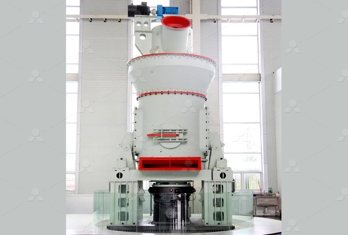
LM Vertical Roller Mill
Input size:38-65mm
Capacity: 13-70t/h
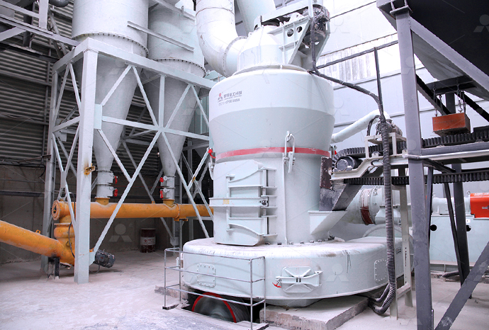
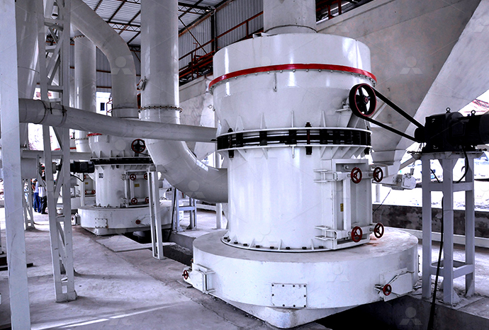
Raymond Mill
Input size:20-30mm
Capacity: 0.8-9.5t/h
Sand powder vertical mill
Input size:30-55mm
Capacity: 30-900t/h
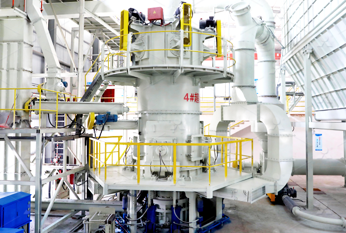
LUM series superfine vertical roller grinding mill
Input size:10-20mm
Capacity: 5-18t/h
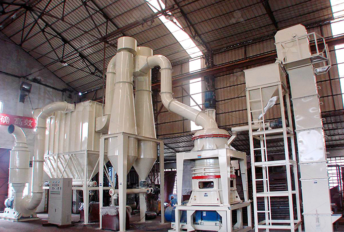
MW Micro Powder Mill
Input size:≤20mm
Capacity: 0.5-12t/h

LM Vertical Slag Mill
Input size:38-65mm
Capacity: 7-100t/h
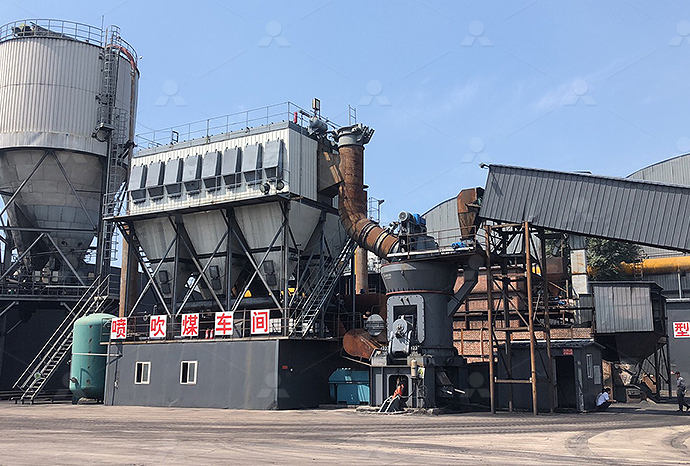
LM Vertical Coal Mill
Input size:≤50mm
Capacity: 5-100t/h
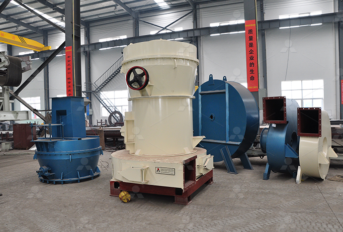
TGM Trapezium Mill
Input size:25-40mm
Capacity: 3-36t/h

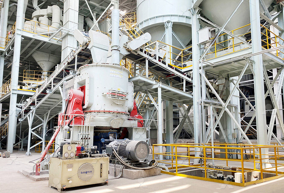
MB5X Pendulum Roller Grinding Mill
Input size:25-55mm
Capacity: 4-100t/h
Straight-Through Centrifugal Mill
Input size:30-40mm
Capacity: 15-45t/h
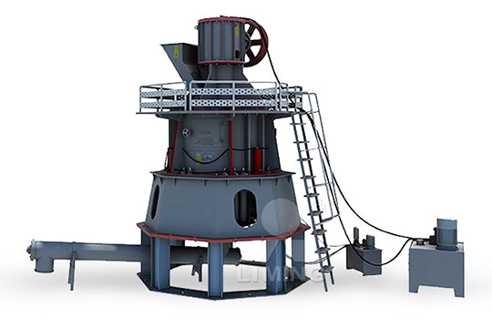
Hydraulic barite grinding machine electrical control diagram
.jpg)
KENT KGS818AH INSTRUCTION MANUAL Pdf
Table and Splash Guard Choice of Site The output of the machine and the degree of accuracy of the components produced depend on the correct choice of site for the position of the machine Grinding machines are often found between TO engage the hydraulic table travel, turn the table speed control lever C„W until desired speed is obtained Hydraulic pressure is unloaded when the lever is in the table stop position Home Sharp Industries IncOn highpressure applications, however, electrical control may become complex and costly because the actuating mechanisms (solenoidoperated hydraulic valves) must be pilot Unit Introduction to Electrical Control of Hydraulic SystemsAll hydraulic units and their connections must be shown on the circuit diagram The hydraulic schematic forms the basis of the pipework of the system and –– together with the function Circuit diagram HAWE Hydraulik
.jpg)
HARIG AUTOMATIC PLC MANUAL Pdf Download ManualsLib
In order to achieve the maximum performance of your new Harig® Surface Grinder, carefully follow these instructions on how to grind the bottom of your magnetic chuck: 1 Check the axis Grinding Machine We believe that this machine is capable of meeting your requirement and to make your product with best high precision quality This brochure is an operation and G32P(A)CNCmanual(Eng)A Sharp Industriessetting, hydraulic oil is released and driving gear wheel goes through the spring and connects with handwheel Operator can control the table with handhweel For hydraulic operation setting, Operation Manual Kent Industrial USATwo special 'Polystrene' packs for dispatch and retention of grinding wheel assemblies and all standard equipment Motors and electrical control gear suitable for operating on 220/250 and Ytl
.jpg)
USA J 1 MAIN PARTS OF THE MACHINE Kent Kent Industrial USA
‘I Wire the machine according to the electric circuit diagram 2 Install the machine with adequate ‘body” clearance beyond the maxium travels 3 Doerator always wears protecting eye View and Download KENT KGS1020M operation manual online Manual Surface Grinder KGS1020M grinder pdf manual downloadKENT KGS1020M OPERATION MANUAL Pdf Download ManualsLib2021年11月23日 This is a small grinder operated with electric power It can be easily carried anywhere Grinding can be done by holding it in hand It is used for cleaning heavy welding jobs On one end of the motor shaft, a grinding wheel 14 Types of Grinding Machines [Working, Diagram 2018年6月8日 Schematic Diagram Of An Injection Molding Machine Scientific Hydraulic Cylinder Ejection Design 8 Main Points Of Injection Mold Injection Molding Machines J220e Injection Molding Machine In Jsw Mh500 Hydraulic Hydraulic Circuit Diagram Of Injection Molding
.jpg)
Unit Introduction to Electrical Control of Hydraulic Systems
Basic principles of electrical control Electrical control is by far the most popular type of automatic control used for industrial hydraulic applications As Figure 12 shows, an electrical control circuit consists of the following parts: 1) Input element(s) 2) Controller 3) Actuating mechanism(s) Figure 12 Breakdown of an electrical control Download scientific diagram Schematic diagram of hydraulic press machine emulator from publication: Control of Hardware Implementation of Hydraulic Servo Application Based on Adaptive Neuro Schematic diagram of hydraulic press machine emulator2022年12月8日 Servohydraulic systems: These systems combine hydraulic power with electrical control In servohydraulic presses, electric motors control the pump, adjusting its speed to match the force and speed requirements of the press This results in lower energy consumption, reduced noise, and improved precisionHydraulic Press Diagram How is Hydraulics used in Presses?2023年8月5日 In this video we can learn Hydraulic Press Machine Starter Control wiring diagramChannel link: https://youtube/channel/UC5irLcuC In this video we exElectrical hydraulic Press Machine Control wiring Circuit
.jpg)
Active Control for Rock Grinding Works of an Underwater
2016年12月6日 T denotes the hydraulic motor torqueP L denotes the load pressure V m denotes the volume of the motor η t denotes the motor’s overall efficiency []Unless the load pressure is given, the motor produces no torque As the hydraulic cylinder imposes the external load on the hydraulic motor, the proportional control valve for the hydraulic cylinder need be This page titled Hydraulics and Electrical Control of Hydraulic Systems (Pytel) is shared under a CC BYNC 40 license and was authored, remixed, and/or curated by Jim Pytel via source content that was edited to the style and standards of the LibreTexts platformHydraulics and Electrical Control of Hydraulic Systems (Pytel)KUGNC1 Series Electrical Print Diagram (220 J4 CE) Electrical : KUGNC2 Series Electrical Print Diagram ACURITE MILLPWR G2 Control: Operation: CNC Bed Mills and Machining Centers; ACURITE MILLPWR G2 Control: Operation: BM3: YOUR MACHINE NOT ON THE LIST?Manuals Kent Industrial USADownload scientific diagram Schematic of a battery powered electro hydraulic forklift with a fixed displacement single direction hydraulic pump and control valves Conventional hydraulic circuit Schematic of a battery powered electro hydraulic forklift with a
.jpg)
Schematic diagram of the grinding machine and
Download scientific diagram Schematic diagram of the grinding machine and instrumentation from publication: Predicting Surface Roughness in Grinding Using Neural Networks The technique of 2019年11月16日 Biger Group Hydraulics Division Business Unit Machinery Press Module For Hydraulic Presses Bosch Rexroth Ag Y32 Four Column Hydraulic Press Operation Manual Machinemfg Interior Design Machines And Hydraulic Press Circuit Diagram Wiring Digital and 2021年5月5日 The grinding machine is widely used to finish the workpiece Do you know why? Because the work removal rate is low between 025 to 05 mm (This can be advantages or disadvantages also for various types of works) Grinding Machine: Definition, Parts, Working PK 50002 (Hydraulic Diagram) Free download as PDF File (pdf), Text File (txt) or read online for free This document contains a hydraulic diagram for a crane It includes a key for various signs and symbols used in hydraulic diagrams, such as signs for different crane components and devices It also includes a key for electrical triggers and feedback signals related to crane PK 50002 (Hydraulic Diagram) PDF Crane (Machine) Machines
INSTRUCTION MANUAL FOR PRECISION SURFACE GRINDER
Packing Diagram 2 1 3 4 1 Machine 2 standard Accessories 3 Coolant Tank 4 Table and Splash Guard C) Choice of Site The output of the machine and the degree of accuracy of the components produced depend on the correct choice of site for the position of the machine Grinding machines are often found between milling, shaping 2019年11月13日 Precision Surface Grinding Machine PSG/ACCGX Series MTR0 OKAMOTO MACHINE Hydraulic and Lubrication Elements relocated outside Saddle Moving Pump Motor Luburication Pump Motor Spindle Head Electrical Control Box Operation Box Column Grinding Wheel Guard using Stainless Steel material Splash cover also available Precision Surface Grinding Machine PSG/ACCGX Series2021年4月12日 Electric Hydraulic Double Acting Directional Control Valve 1 Spool Hydraulic Molock Solenoid Directional Control Valve 1 Spool 21 Gpm 4wemm6 Solenoid Manual Directional Control Valve Hydraulic China Rexroth And Hydraulic Solenoid Valve How They Work Tameson Com How To Wire Hydraulic Power Pack Unit Diagram Design How Silt Lock Can How To Wire A Hydraulic Solenoid Valve » Wiring WorkDifferent Types of Electrical Wiring Circuit Diagrams and Drawings In Electrical and Electronics Engineering, we use different types of drawings or diagrams to represent a certain electrical system or circuitThese electrical circuits are represented by lines to represent wires and symbols or icons to represent electrical and electronic componentsIt helps in better understanding the Types of Electrical Drawings and Wiring Circuit Diagrams
Home Sharp Industries Inc
(1) Electrical equipment (refer to the wiring diagram) The electrical equipment of the machine consists of the folloving items : Electric motor for grinding wheel Electric motor for dust suction system Electric motor for cross movement Lubricating pump Hydraulic pump motor Working lamp 075kw 2P 04kw 2P 25 w 1 ow 075kw 6P 60W2024年11月19日 Stay uptodate with the latest hydraulic shearing machine technology with our comprehensive guide Discover the benefits, Electrical Diagram ** Hydraulic schematic diagram Here are the drawings: The oil in the upper chamber of the right cylinder can only enter the hydraulic control singleway valve S3 (at this point, Hydraulic Shearing Machine: The Ultimate Guide MachineMFG(4)When insp ecting electrical sections of the machine,insulating gloves,rubber or leather boots and other nonconducting protective items should be used (5)Electrical parts need earthing must be earthed according to the diagrams (6)Before inspecting electrical circuits,first confirm with instruments that the circuit is turned offINSTRUCTION MANUAL FOR PRECISION SURFACE GRINDER Hydraulics Systems Diagrams and Formulas for a front end loader, winch, logsplitter, and other useful formulas The above system shows a front end loader powered by a PTO driven pump A 2spool directional control valve Hydraulics Systems Diagrams and Formulas Cross
.jpg)
Hydraulic Cylindrical Grinding Machine at Best Price from
2017年1月2日 Find Hydraulic Cylindrical Grinding Machine manufacturers, Power Source Electricity Operating Type Semi Automatic More details Tespa India Pvt Ltd High Efficiency 500X250X330 Mm Plc Control 240 Volt Automatic Hydraulic Cylindrical Grinding Machine INR Star Enterprises2024年11月7日 The grinding precision on the machine is guaranteed and every control in the machines is within the easy reach of the operators Prayosha Enterprise provides a surface grinding machine in India, a versatile equipment that is Hydraulic Surface Grinding Machine Manufacturer IndiaPrecision grinding machine shall not be adjacent to machines such as planing machine, milling machine, molding or puching machine Otherwise, it will result in poor grinding accuracy 2 DIAGRAM OF MACHINE SPACE : unit:mm MODEL A B C 1545M 2045M 2600 2100 1700 1545H/AH 2045H/AH 3080 2200 1700 2550H/AH 3250 2400 2000 C/D3060AH 3650 2550 2100INSTRUCTION MANUAL MachineryhouseIn this study, modifying a constant speed–driven hydraulic press brake machine into a variable speed drive system is examined in terms of electricity saving, CO2 reduction, and economic Hydraulic circuit schema of a press brake driven by constant speed
.jpg)
Hydraulic Circuit Diagram For Milling Machine
2017年9月23日 In this blog article, we’re going to explain how hydraulic circuits are used in milling machines, as well as provide an example of a typical hydraulic circuit diagram for a milling machine The hydraulic circuit diagram is a key tool that allows engineers to effectively control a mill which can be operated by hydraulic actuatorsManufacturer of HYDRAULIC SURFACE GRINDER Hydraulic Surface Grinding Machine offered by Bhavya Machine Tools, Ahmedabad, Gujarat Bhavya Machine Tools Odhav, Ahmedabad, Gujarat PIPE BENDING MACHINE; ELECTRIC TAPPING MACHINE; HYDRAULIC SHEARING MACHINE +View All ;HYDRAULIC SURFACE GRINDER Hydraulic Surface Grinding Machine 2022年6月8日 Pilot pressure and electric actuation are the dominant forces in the market and will be for some time Electronic control systems allow for the precise application for pilot actuation (left), where low pressure shifts the valve, and electroproportional actuation The right schematic symbol is for a solenoid operationThe Best Way to Read a Hydraulic Schematic Mentored Engineer2023年10月1日 3 Grinding Machine : The machine structure provides the static and dynamic constraints between the tool and the workpiece Type of machines to be selected depends upon the type of operations to be performed A perfectly designed grinding machine should experience less vibrations and provide high accuracy movementsWhat is Grinding? Process, Machine, Parts ElectricalWorkbook
.jpg)
Atul Machine Hydraulic Surface Grinding Machine
Unit 1 Atul Machine Tools Grinding Machine Manufacturing Unit Plot No P103, Kalawad Road, GIDC, Metoda, Rajkot, Gujarat , India Mr Ravi: +91 – 87584 年8月16日 Ironworker Hydraulic System Diagram 3 Ironworker Hydraulic System Diagram 4 Ironworker Hydraulic System Diagram 5 Ironworker Hydraulic System Diagram 6 Electric System (1) Introduction: The hydraulic steelworker Q35Y Hydraulic Ironworker Operation Manual Download scientific diagram Hydraulic cylindrical grinding machine from publication: Experimental investigation of the effects of process parameters on material removal rate using Taguchi Hydraulic cylindrical grinding machine Download 2 Unit: mm Function Item Model 500 600 1000 1500 2000 Grinding Wheel Table Grinding Wheel Infeed Manual Button Feed 00025 Tailstock Lathe Center Range 30 Lathe Center MT4 Driving Motor Grinding Table Motor 37kw 5HP 4P Workstation Motor 04kw 1/2HP 4P Hydraulic Motor 075kw 1HP 4P 15kw 2HP 4POperation Manual Kent Industrial USA
.jpg)
Basics of DirectionalControl Valves Power Motion
2019年6月5日 2 Schematic shows simple circuit to control cylinder extension and retraction using a 4port, 3position spool valve Spooltype valves are widely used because they can be shifted to two, three, or more positions for routing fluid between different combinations of 2022年12月1日 Hydraulic control schematic diagram Working principle: First, open the main switch and connect the oil circuit The signal obtained by the twoposition, threeway reversing valve is placed in the Design of hydraulic pneumatic control system for rail grinding carGraphic Symbols for Electrical and Electronic Diagrams (Including Reference Designation Letters) ANSI Y329: Electrical Wiring Symbols for Architectural and Electrical Layout Drawings: The hydraulic control mechanism controls the flow to the stroke control shaft, which positions the tilting box in the Aend of the transmissionBasic Diagrams and Systems Engineering LibraryTwo special 'Polystrene' packs for dispatch and retention of grinding wheel assemblies and all standard equipment Motors and electrical control gear suitable for operating on 220/250 and 380/440 standard voltages, 3 phase, 50 cycles supply Extra Equipment (to order) Motordriven dust control unit, standard voltageYtl
.jpg)
Schematic circuit diagram of a conventional hydraulic tube
Download scientific diagram Schematic circuit diagram of a conventional hydraulic tube bender from publication: Design of a Novel Energy Efficient Hydraulic Tube Bender Generally speaking Figure 27 Simple Hydraulic Power System Figure 28 Line Diagram of Simple Hydraulic Power System With an understanding of the principles involved in reading fluid power diagram, any diagram can be interpreted Figure 29 shows the kind of diagram that is likely to be encountered in the engineering fieldHydraulic and Pneumatic PID Diagrams and Schematics