


MTW European Type Trapezium Mill
Input size:30-50mm
Capacity: 3-50t/h
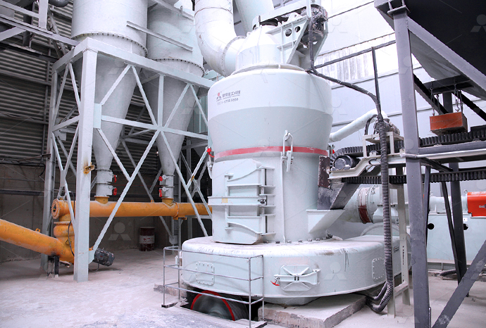
LM Vertical Roller Mill
Input size:38-65mm
Capacity: 13-70t/h
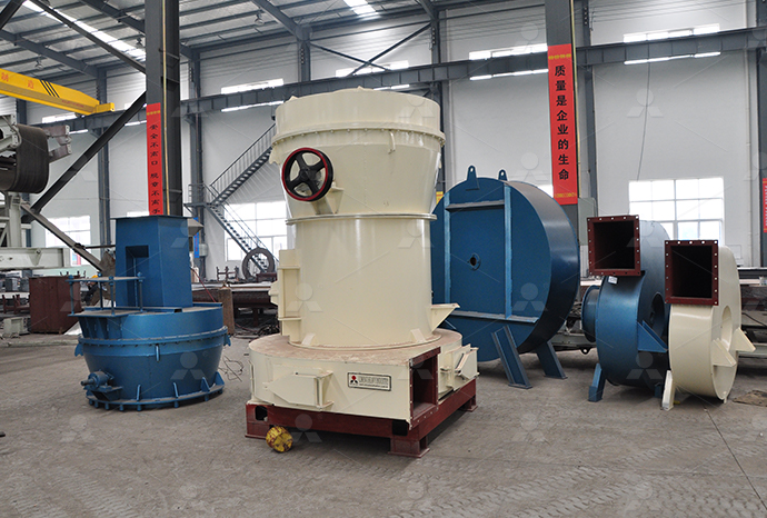
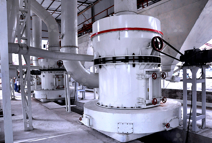
Raymond Mill
Input size:20-30mm
Capacity: 0.8-9.5t/h

Sand powder vertical mill
Input size:30-55mm
Capacity: 30-900t/h

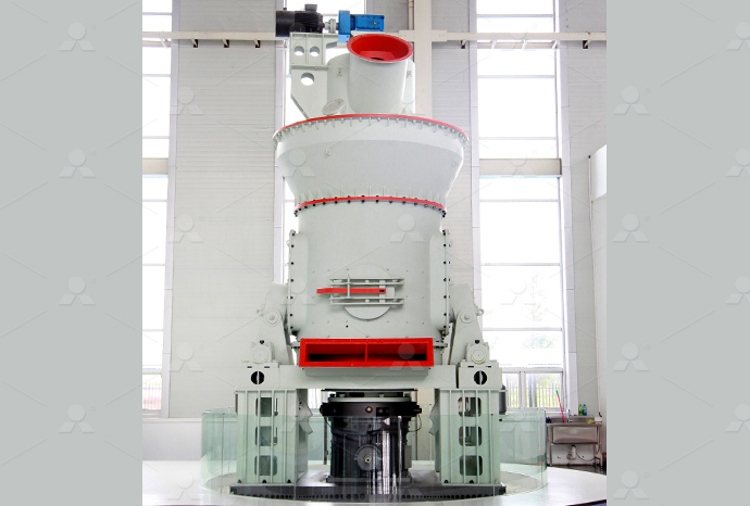
LUM series superfine vertical roller grinding mill
Input size:10-20mm
Capacity: 5-18t/h
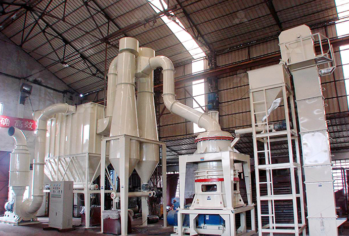
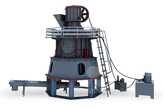
MW Micro Powder Mill
Input size:≤20mm
Capacity: 0.5-12t/h

LM Vertical Slag Mill
Input size:38-65mm
Capacity: 7-100t/h

LM Vertical Coal Mill
Input size:≤50mm
Capacity: 5-100t/h
TGM Trapezium Mill
Input size:25-40mm
Capacity: 3-36t/h

MB5X Pendulum Roller Grinding Mill
Input size:25-55mm
Capacity: 4-100t/h
Straight-Through Centrifugal Mill
Input size:30-40mm
Capacity: 15-45t/h
120 barite mill hydraulic oil circuit diagram
.jpg)
INDUSTRIAL HYDRAULIC CIRCUITS IDCOnline
Typical hydraulic circuits for control of industrial machinery are described in this lesson Graphical hydraulic circuit diagrams incorporating component symbols are used to explain the operation All hydraulic units and their connections must be shown on the circuit diagram The hydraulic schematic forms the basis of the pipework of the system and –– together with the function Circuit diagram HAWE HydraulikA pump delivers oil at a rate of 182 gallons/min into the blank end of a cylinder of diameter 75 mm (Fig 131) The piston contains a 25 mm diameter cushion plunger that is 25 mm; Lecture 26 HYDRAULIC CIRCUIT DESIGN AND ANALYSISFigure shows a circuit where speed control of a hydraulic motor ( Bi directional motor) is accomplished using a flow control valve to control the fluid flow to the motor In the spring LECTURE 24 TO 26 HYDRAULIC CIRCUIT DESIGN FREQUENTLY
.jpg)
Lesson 28 Hydraulic circuit diagrams and troubleshooting
Hydrauliccircuit diagrams are complete drawings of a hydraulic circuit It includes the description, a sequence of operations, notes, and a components list Such diagrams are essentially Identify the graphic symbols for various types of hydraulic components Explain various hydraulic circuits to control singleacting and doubleacting cylinders Explain a regenerative circuit and Lecture 24 HYDRAULIC CIRCUIT DESIGN AND ANALYSISBeginning of oil hydraulics: Williams and Janney use mineral oil as a transmission medium for hydrostatic transmissions for the first time The engineer Hans Thoma invents the radial piston Hydraulics Basic Principles Bosch Rexroth WE MOVE YOU WIN• The above figure shows a hydraulic circuit to operate bidirectional motor using a tandem center 4/3 DCV • In first position of 4/3 DCV, oil flows from P – A and B – T Hence the motor runs in Oil Hydraulic Circuits pcpolytechnic

Compact knowledge Hydraulics – Basic principles Bosch Rexroth
was developed In this series, "Hydraulics − Basic principles" offers an overview of the basic principles and components of hydraulic systems such as on/off valves, hydraulic pumps, Hydraulic circuits are developed through the use of graphical symbols for all components Before hydraulic circuits can be understood, it is necessary to know these fluid power symbols Next Basic Hydraulic Circuit Design and Analysis DrRolaCircuit Diagram is a free application for making electronic circuit diagrams and exporting them as images Design circuits online in your browser or using the desktop applicationCircuit Diagram A Circuit Diagram MakerFigure 122: Hydraulic system pictorial diagram Cutaway Diagrams Cutaway diagrams (Figure 123) show the internal working parts of all fluid power components in a system The diagrams include controls and actuating Basic Diagrams and Systems Engineering Library
.jpg)
Reading fluids circuit diagrams hydraulic circuit
2018年1月2日 Oil lines to "tank" usually have 1530 psi of backpressure as they are passed through oil filters before entering the tank For more information about reading hydraulic and pneumatic circuit diagrams, read the next article in this Oil Circuit Diagrams 700R4MD8 Free download as PDF File (pdf), Text File (txt) or read online for free This document provides a diagram of the hydraulic system of a HydraMatic 700R4 transmission It labels the various components such as clutches, valves, accumulators, and pressures involved in shifting between gears while in the "D4" drive modeOil Circuit Diagrams 700R4 MD8 PDF Manual Transmission Hydraulic Circuits and Components This study guide will discuss basic hydraulic systems We will look at fundamental principles and how they pertain to hydraulic systems We will also learn about various hydraulic components and their function A hydraulic circuit, whether it is simple or complex uses the basic hydraulic principles discussed on theHydraulic Systems Basics Toro2020年9月6日 This Complete Service Repair Workshop Manual PDF Download for the Komatsu PC1006 (SN: 40001 and up), PC1206 (SN: 45001 and up) Hydraulic Excavator has easy to read text sections with top quality diagrams, pictures and illustrationsKomatsu PC1006, PC1206 Hydraulic Excavator Shop Manual –

Lecture 26 HYDRAULIC CIRCUIT DESIGN AND ANALYSIS
We know that the oil supplied by the accumulator after charging isv 3−v 2 This is used for the cylinder displacement for crushing The amount of oil required for crushing with the given constructional details as calculated above is 4488 ×10–2 m3 Therefore, equating the above volume required, we get v 3−v 2 =4488 ×10 –2 m3 166 v 2 Components of a Hydraulic Circuit Diagram In a hydraulic circuit, various components are used to direct the flow of fluid and control the movement of mechanical parts These components work together to create a reliable and efficient hydraulic system A hydraulic circuit diagram is a graphical representation of these components and their A Comprehensive Guide to Hydraulic Circuit Diagrams in PDF MAINTENANCE Change Hydraulic Oil Suction Filter Cleaning every 5000 hours, 2500 hours or 1500 hours CAUTION: Hydraulic oil may be hot just after opera M10407117 tion Wait for oil to cool before starting work IMPORTANT: Hydraulic oil changing intervals differ ac cording to kind of hydraulic oils used Page 224 MAINTENANCE 12HITACHI 1203 CLASS OPERATOR'S MANUAL Pdf DownloadSequence Valve of the Hydraulics Trainer does not have a builtin check valve, so an external check valve must be connected across it when reverse flow is required Figure 32 shows the Check Valve of the Hydraulics Trainer The valve consists of inlet and outlet ports, a ball, and a light spring When the pressure of the oil at theHydraulic Sequencing of Cylinders Philadelphia University
.jpg)
Oil Hydraulic Circuits pcpolytechnic
• The above figure shows a hydraulic circuit to operate bidirectional motor using a tandem center 4/3 DCV • In first position of 4/3 DCV, oil flows from P – A and B – T Hence the motor runs in clockwise direction • In second position 4/3 DVC oil flows from P – B and A – T Hence the motor runs in anticlockwise direction5 With the help of circuit diagram explain Double Pump Hydraulic system In the closed circuit drive, exhaust oil from the motor is returned directly to the pump inlet Variable displacement pump M R Open circuit (open loop ) HST PUMP MOTO R Figure shows a closed circuit that allows either direction of LECTURE 24 TO 26 HYDRAULIC CIRCUIT DESIGN FREQUENTLY Graphical hydraulic circuit diagrams incorporating component symbols are used to explain the operation of the circuits Case Study I: In Figure 281 below, when both pumps are delivering, oil from the pump A passes through the unloading valve C and the check valve D to combine with the pump B output This continues soINDUSTRIAL HYDRAULIC CIRCUITS IDCOnline41 Circuit diagrams in hydraulics 297 411 Graphical illustration of hydraulic circuits 297 42 Open and closedloop control with valves 300 421 Openloop control with directional control valves 300 422 Velocity control with throttle valves 304 423 Loadindependent velocity control with flow control valves 309 424 Rapid traverse Hydraulics Basic Principles Bosch Rexroth WE MOVE YOU WIN
How to read hydraulic circuits
How to read hydraulic circuits Information about the device of the hydraulic system is shown on the hydraulic diagram using symbols Hydraulics schematic symbols are a basic component of hydraulic circuit Symbols for hydraulic systems are for functional interpretation and comprise one or more function symbolsOil Circuit Breaker Diagram: In such Oil Circuit Breaker Diagram, some insulating oil (eg, transformer oil) is used as an arc quenching medium The contacts are opened under oil and an arc is struck between them The heat of the arc evaporates the surrounding oil and dissociates it into a substantial volume of gaseous hydrogen at high pressureOil Circuit Breaker Diagram Types of Oil Circuit Breaker2022年6月8日 In every hydraulic system, you will have one function that requires full flow and another that needs much less flow This is where flow reducers come in The most basic type is an orifice which is a hole drilled in what would otherwise be a plug As you can imagine, there is a fixed amount of oil that can be pushed through the holeThe Best Way to Read a Hydraulic Schematic Mentored Engineer2017年12月19日 Field Report How to read fluids circuit diagrams, Part 1 Symbols; Field Report How to read fluids circuit diagrams, Part 2 Hydraulics; Field Report How to read fluids circuit diagrams, Part 3 Pneumatics; Field Report Common hydraulic valves, cartridge pressure relief valves; Field Report Common hydraulic valves, pressure reducing valvesReading fluids circuit diagrams hydraulic pneumatic symbols
Schematic diagram of the hydraulic system 1: oil tank, 2: ball
Download scientific diagram Schematic diagram of the hydraulic system 1: oil tank, 2: ball valve, 3: strainer, 4: proportional relief valve, 5: proportional pump 2018年4月22日 Hitachi Lx110 7 Hydraulic Circuit Diagram Hitachi Zx35u 5b Hydraulic Excavator Electrical Circuit Diagram Manual Pdf Heys S Jcb Js300 Js330 Js370 Tracked Excavator Service Manual Sweeper Collector Hydraulic Circuit Construction Jcb 3cx 4t Regular Backhoe Loader Centremount 9802 9760 M Attachments Shovels 777partsHydraulic Circuit Diagram Of Jcb Wiring Digital and SchematicHydraulic schematic symbols are standardized graphical representations used to depict the components of hydraulic systems on schematic diagrams These symbols allow pressure relief valves, and critical actuators Understanding Hydraulic Schematic Symbols Piping Technology Download scientific diagram crane booming hydraulic system circuit employing the investigated load control valve from publication: Research on Characteristics and Key Design Parameters of a Fig 1 crane booming hydraulic system circuit

The Ultimate Hydraulic Oil Guide Hydraulics Online
The hydraulic oil longevity depends on a few influences: the quality of the oil, working conditions and possibly even contamination However, within the right environmental factors, a high quality oil should be able to last at least six 2024年11月19日 4 Change Hydraulic Oil Regular replacement of hydraulic oil is crucial for maintaining the shearing machine’s performance Follow these steps: Initial Replacement: Replace the hydraulic oil after the first 2000 hours of operation Subsequent Replacements: Replace the oil every two years or after 4000 hours of useHydraulic Shearing Machine: The Ultimate Guide MachineMFGHydraulic Circuit Diagrams The circuit diagrams are used in hydraulics to show the components along with their interaction Abrasive matter in the hydraulic oil is being circulated Put a proper filter to check dust particles Control valve sticky or working hard Misalignment in Lesson 28 Hydraulic circuit diagrams and troubleshooting2015年12月6日 1 HYDRAULIC PNEUMATIC SYSTEMS HYDRAULIC SYSTEMS FOR SUGAR MILLS MINI SUGAR MILLS ACE Sugar Mill Hydraulic Systems are based on over 30 years of experience in sugar, paper, steel other rolling mill applications In sugar mills the main objective is to apply hydraulic pressure on the crushing roll hydraulic mill caps The system Hydraulic Systems for Sugar Mills PDF SlideShare
.jpg)
Basic Hydraulic System Components, Design Circuit Diagram
Types Of Hydraulic Motors And Their Symbol Used in Hydraulic Circuit Diagram 4 Hydraulic Cylinder Hydraulic cylinder is a mechanical hydraulic actuator that converts hydraulic energy or hydraulic pressure into linear displacement It consists of cylindrical barrel, piston and piston rod Types of Hydraulic Cylinder and Their Symbol Used In A hydraulic circuit diagram for a doubleacting cylinder is a schematic representation of the hydraulic components and their interconnections When pressurized fluid, such as hydraulic oil, is supplied to one side of the cylinder, it pushes the A Visual Guide to the Hydraulic System of a Double Acting CylinderThe hydraulic circuit for a milling machine is comparatively different from the hydraulic circuit of the surface grinding machine and hydraulic circuit of the shaper machineThis is because the table movement in milling operation is comparatively slower Also, the different feeds or you can say adjustable feeds are required for milling different types of workHydraulic Circuit for Milling Machine Explained In DetailsComment on advantages and disadvantages of pressure intensification for series hydraulic circuits Given an intensifier with the following dimensions, calculate the output pressure given an input pressure of 80psi d in = 3” d out = 3/4” Describe flow paths in 31 Series and Parallel Hydraulic Circuits – Hydraulics and

Hitachi EX1205 Excavator Factory Service Shop
2018年8月22日 T155E00CIR – Hitachi EX1205 Excavator Electrical Circuit Diagram EM1E8NA21 – Hitachi EX1205 Excavator Operator’s Manualpdf TO155E02 – Hitachi EX1205 Excavator Technical Manual (Operational Before selecting hydraulic directional spool valves, it must be sure to choose appropriate spool valve in neutral position as per requirements of hydraulic system For example: 1 Design pressure unloading circuit by spool function in Hydraulic Spool Valve Diagram Hydraulic Valves 2024年7月30日 Hydraulic Oil: Serves as the power and efficiency in hydraulic circuits Directional valve The primary function of a directional valve is to manage fluid flow paths within hydraulic systems Appendix: Schematic Diagram Of Press Brake Hydraulic System Explained (diagram)Page 1 BAYKAL USER’S MANUAL HYDRAULIC PRESS BRAKE MODEL APHS No part of this User‘s Manual may be reproduced or transmitted by any without Prior permission of Baykal Makine Sanayi ve Ticaret A EDITION NO APHS DATE OF ISSUE : May2011 Page 2 BAYKAL MACHINE TYPE DESCRIPTION APHS XXXXXxx SUPPLY HYDRAULIC BAYKAL APHS SERIES USER MANUAL Pdf Download ManualsLib
.jpg)
Hydraulic and Pneumatic PID Diagrams and Schematics
Figure 27 Simple Hydraulic Power System Figure 28 Line Diagram of Simple Hydraulic Power System With an understanding of the principles involved in reading fluid power diagram, any diagram can be interpreted Figure 29 shows the kind of diagram that is likely to be encountered in the engineering field2014年2月6日 How to read hydraulic circuits Hydraulics symbols are an essential component of hydraulic circuit diagrams Knowing some of the basic principles will help understand a wider range of symbols Explaining the common ISO1219 symbols enables a complete hydraulic system to be followed: 1 Hydraulic Pump Hydraulic pump produces flow Oil is pumped from the How to read hydraulic circuits Hydra Products2019年5月1日 Ever tried to decipher a hydraulic circuit diagram and make sense of its symbols? Our blog will help you to understand the meanings and functions of the common ISO1219 hydraulic symbols As there are so many possible combinations of system parts and functions possible, we look at the base component circuits that make up a typical hydraulic power unitHow do I decipher a hydraulic circuit diagram? PART 1Hydraulics Systems Diagrams and Formulas for a front end loader, winch, logsplitter, and other useful formulas The tank should be at least one and a half times the pump gpm output and the oil level must remain above the pump intake at all times (See Logsplitter Safety for Hydraulics Systems Diagrams and Formulas Cross MFG
Principles of the hydraulic control system of the Rautaruukki hot
Download scientific diagram Principles of the hydraulic control system of the Rautaruukki hot rolling mill from publication: Intelligent Techniques for Condition Monitoring of Rolling Mill 4 Basic circuits 135 41 Circuit diagrams in hydraulics 135 411 Graphical illustration of hydraulic circuits 135 42 Valve control circuits 138 421 Control with directional control valves 138 422 Velocity control with throttle valves 144 423 Loadindependent velocity control with Compact knowledge Hydraulics – Basic principles Bosch