


MTW European Type Trapezium Mill
Input size:30-50mm
Capacity: 3-50t/h

LM Vertical Roller Mill
Input size:38-65mm
Capacity: 13-70t/h

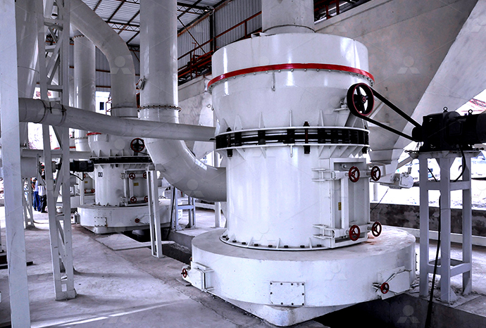
Raymond Mill
Input size:20-30mm
Capacity: 0.8-9.5t/h

Sand powder vertical mill
Input size:30-55mm
Capacity: 30-900t/h

LUM series superfine vertical roller grinding mill
Input size:10-20mm
Capacity: 5-18t/h

MW Micro Powder Mill
Input size:≤20mm
Capacity: 0.5-12t/h

LM Vertical Slag Mill
Input size:38-65mm
Capacity: 7-100t/h

LM Vertical Coal Mill
Input size:≤50mm
Capacity: 5-100t/h
TGM Trapezium Mill
Input size:25-40mm
Capacity: 3-36t/h

MB5X Pendulum Roller Grinding Mill
Input size:25-55mm
Capacity: 4-100t/h

Straight-Through Centrifugal Mill
Input size:30-40mm
Capacity: 15-45t/h
Barite mill hydraulic station schematic diagram

Sag schematic diagram of barite and Mn3O4
Download scientific diagram Sag schematic diagram of barite and Mn3O4 from publication: Micromanganese as a weight agent for improving the suspension capability of drilling fluidThe hydraulic schematic forms the basis of the pipework of the system and –– together with the function diagram — forms the basis of the search for an error The schematic is designed in Circuit diagram HAWE HydraulikTypical hydraulic circuits for control of industrial machinery are described in this lesson Graphical hydraulic circuit diagrams incorporating component symbols are used to explain the operation INDUSTRIAL HYDRAULIC CIRCUITS IDCOnlineReading and Interpreting Hydraulic Schematic Symbols Sullivan Page 1 The secret to being successful at reading and interpreting a schematic for a hydraulic system is really quite simple The Secret of Hydraulic Schematics

Reading fluids circuit diagrams hydraulic circuit examples Valmet
2018年1月2日 This article will describe three example hydraulic schematic diagrams Hydraulic (oil under pressure) controls are used when very heavy components must be moved with Identify the graphic symbols for various types of hydraulic components Explain various hydraulic circuits to control singleacting and doubleacting cylinders Explain a regenerative circuit and Lecture 24 HYDRAULIC CIRCUIT DESIGN AND ANALYSISSuccessful applications of horizontal drilling combined with hydraulic fracturing (HF) techniques, first demonstrated in the Texas Barnett shales in the 1990s, are the impetus for the current (a) Barite schematic with crystallographic indices labeled (b) Barite Understanding the schematic diagram of a hydraulic system is essential for designing, constructing, and maintaining hydraulic systems It allows technicians to identify and locate The Ultimate Guide to Understanding Schematic Diagrams of

Hydraulics Basic Principles Bosch Rexroth WE MOVE YOU WIN
Each training system consists of the workstation, the components contained in the device sets and the exercise books The training systems provide both beginners and advanced trainees The diagram shows a winch powered by a hydraulic motor The directional control valve with builtin relief features optional flow control to control the speed of the winch The hydraulic pump and motor must be matched to the torque Hydraulics Systems Diagrams and Formulas Cross Hydraulic schematic symbols play a crucial role in visualizing hydraulic systems as they provide a standardized method of representing hydraulic components and their interconnections These symbols allow engineers and technicians to Understand the Basics: Decoding Hydraulic Schematic Download scientific diagram Schematic diagram of mechanicalhydraulic coupling system of rolling mill from publication: Adaptive Fuzzy Vertical Vibration Suppression Control of the Mechanical Schematic diagram of mechanicalhydraulic coupling
.jpg)
System schematics for aroTHERM plus Vaillant
aroTHERM plus with DHW Cylinder, Hydraulic Station, Decoupler, 1 Radiator Zone 39 aroTHERM plus with DHW Cylinder, Hydraulic Station, Decoupler, 1 Terms and Conditions for Vaillant Schematic Diagrams PLEASE NOTE THAT THE DIAGRAM PROVIDED IS FOR GENERAL INFORMATION PURPOSES ONLY THE ADVICE AND INPUT OF A Download scientific diagram The schematic diagram of hydraulic roll bending technique from publication: Prediction of Bending Force in the Hot Strip Rolling Process Using Multilayer Extreme The schematic diagram of hydraulic roll bending techniqueHydraulic schematics provide a visual representation of the system’s flow and enable engineers and technicians to analyze and optimize system performance Importance of Hydraulic Schematic Legends Hydraulic schematic legends play a crucial role in understanding and interpreting hydraulic system diagramsHydraulic schematic legend Wiring Diagrams FreeDownload scientific diagram Simplified schematic of a hydroelectric power plant from publication: In electrohydraulic speed governors, circuits providing compensation deploy Proportional Simplified schematic of a hydroelectric power plant
.jpg)
Introduction To Hydraulic And Pneumatic Schematic Diagrams
2019年8月10日 Hydraulics Versus Pneumatics Knowledge Centre Essentra Components Uk Pneumatic Circuit Symbols Explained Library Automationdirect Reading Fluids Circuit Diagrams Hydraulic Pneumatic Symbols Chapter 5 Pneumatic And Hydraulic Systems Power Motion Hydraulic And Pneumatic P Id Diagrams Schematics Inst Tools Chapter 5 Pneumatic And Schematic Symbols (Part 2) Name Designators and Values Reading Schematics Resources and Going Further Overview Schematics are our map to designing, building, and troubleshooting circuits Understanding how to read and follow schematics is an important skill for any electronics engineer This tutorial should turn you into a fully literate How to Read a Schematic SparkFun LearnWe stock replacement parts and diagrams for all of our vises and work holding solutions Kurt Toggle Toggle Menu Workholding Single Station Vises; Double Station Vises; TriLock Vises; 5Axis Vises; Hydraulic Workholding; Pneumatic Workholding; Towers Hydraulic Intensifier APD50112; APD60112 Replacement Parts/Parts Diagrams Kurt WorkholdingDownload scientific diagram Schematic diagram of the electrohydraulic servosystem [7] from publication: Adaptive Control of the ElectroHydraulic ServoSystem with External Disturbances The Schematic diagram of the electrohydraulic servo
.jpg)
Hydraulic system diagram: practical tips and
2024年4月19日 Hydraulic Systems functioning: The basics In general, hydraulic systems for civilian use are divided into two main types: Water supply and distribution (hot and cold), coming from the water supply system or tank;; 2019年12月13日 If you work with hydraulic machinery, it’s essential to know how to read the schematics that make up its complex inner workings But with the vast number of diagrams and symbols used in hydraulic schematics, deciphering How To Read Hydraulic Schematics For Dummies2024年8月4日 Fig3 80,000 Ton Die Forging Press The 80,000ton dieforging hydraulic press stands 27 meters tall on the ground and 15 meters underground, making it a total height of 42 meters and a total weight of 22,000 tons, thereby earning its title as the world’s most powerful and strongest hydraulic pressHydraulic Press Machine 101: Everything You Need to Know Download scientific diagram (a) Barite schematic with crystallographic indices labeled (b) Barite crystal synthesized at room temperature (22 ± 05 °C with 05 mM BaCl 2 : 05 mM Na 2 SO 4 : (a) Barite schematic with crystallographic indices labeled (b) Barite

Circuit diagram HAWE Hydraulik
HAWE Hydraulik develops and produces hydraulic components and systems for mechanical and plant engineering Contact; Customer All hydraulic units and their connections must be shown on the circuit diagram The hydraulic schematic forms the basis of the pipework of the system and –– together with the function diagram — forms Download scientific diagram A schematic diagram of a planetary ball mill (crosssection) from publication: Discrete Element Simulation of the Dynamics of High Energy Planetary Ball Milling A schematic diagram of a planetary ball mill (crosssection)Download scientific diagram Schematic diagram of a hydropower station from publication: Gridconnection analysis of Hydroturbine Generator Unit with Stochastic Disturbance Here, the authors Schematic diagram of a hydropower station ResearchGateDownload scientific diagram Schematic diagram of the equipment on a hydraulic fracturing site The flow path of the fracfluid is from right to left of the schematic In this schematic the red Schematic diagram of the equipment on a hydraulic fracturing
.jpg)
diagram of plant mill Razorite Olivedale
Diagram Of Plant Mill mylightshoeandfriends 16102018 Raw mill diagram in cement plant Raw mill diagram in cement plant cement manufacturing process flow chart in the cement manufacturing process most material must be broken such as limestone iron ore clay and coal etc limestone is the main raw material for cement production each producing a ton of clinker 2 Schematic Circuit Diagrams the “shorthand” system of the industry, are usually preferred for troubleshooting A schematic diagram is made up of simple geometric symbols for the components and their controls and connections Symbol Systems There are several systems of symbols used when making schematic diagrams They are as follows: I S Section 35 Chapter 12017年8月15日 Out of any topic under the patiosized umbrella of fluid power, hydraulic symbology garners the most requests from those wishing to learn more about fluid power Reading any schematic with more than three symbols can Hydraulic symbols: Understanding basic fluid power Hydraulic Mid Inlets 29 Power Beyond 30 Open Center Schematic 31 Closed Center LS Schematic 32 Horse Power Consumption 33 Hydraulic Cylinders 34 Single Acting Double Acting Cylinders 35 Bleeding Air 36 Hydraulic Motor Types 37 How Motors Work 38 Filtration 39 How Filters are Selected 40 PTO Types 41 Manual PTO’s 42Training Basic Hydraulics Parker Hannifin

INDUSTRIAL HYDRAULIC CIRCUITS IDCOnline
• Interpret hydraulic system symbols and circuit diagrams • Describe techniques for energy saving in hydraulic systems Introduction Typical hydraulic circuits for control of industrial machinery are described in this lesson Graphical hydraulic circuit diagrams incorporating component symbols are used to explain the operation of the circuits2014年1月15日 Recently our internal hydraulics group was informed that Creo Schematics 20 will be the new tool for creating hydraulic schematics Unfortunately I have little experience with this software but I am very familiar with other PTC products such as ProE wildfire 4 and now Creo 20 Does anyone in the Help with Creating Hydraulic Schematics in Creo SchematicsFor hydraulic schematic drawings visit us online or contact our team now Trigon Scheme B low volume DHW dual collector with 1 calorifier aux boiler and advanced transfer station Trigon schematics, hydraulic schematic drawing, hydraulic schematics Type: Hydraulic schematics Hamworthy HeatingSchemeit – Schematic Drawing and Block Diagramming Made Easy Schemeit is an online schematic and diagramming tool that allows anyone to design and share electronic circuit diagramsThe tool includes a comprehensive electronic symbol library and an integrated DigiKey component catalog that allows for a wide range of circuit designsFree Online Schematic and Diagramming Tool SchemeIt

Schematic illustration of a tumbling mill Download Scientific Diagram
Download scientific diagram Schematic illustration of a tumbling mill from publication: Effect of operational variables on ball milling Ball mills have large applicability in the mining industry2017年8月15日 By Josh Cosford, Contributing Editor Out of any topic under the patiosized umbrella of fluid power, hydraulic symbology garners the most requests from those wishing to learn more about fluid power Reading any schematic with more than three symbols can be daunting if your experience is limited But it’s not impossible to learn In fact,Hydraulic symbology 101: Understanding basic fluid power schematicsDownload scientific diagram Schematic diagram of a coalfired steam power plant [11] from publication: Hot Corrosion Erosion Problems in Coal Based Power Plants in India and Possible Schematic diagram of a coalfired steam power plant [11]2024年11月7日 Example of Diagram Reading Now let’s go back to industrial diagrams, primarily focusing on schematic diagramsA site electrician, for each system and distribution cabinet, has a set of plans in A3 and/or A4 format with A practical handbook for reading and analysing
.jpg)
Schematic Diagram A Complete Tutorial with Free
The idea of schematic diagrams came into existence somewhere in 1300 AD when the firstever geographical map, which is now known as Atlas, was drawn Later, the same concept was used to draw the maps of stars and Download scientific diagram Schematic of the hydraulic power station layout from publication: MODELLING, SIMULATION AND CONTROL OF A HYDROELECTRIC PUMPED STORAGE POWER STATION In this paper Schematic of the hydraulic power station layoutHydraulic Circuit Diagram with Explanation In a hydraulic system, a circuit diagram is a graphical representation of the different components and connections that make up the system It shows how the fluid flows through the system and how the different components interact with each other to perform specific tasksUnderstanding Hydraulic Circuit Diagrams: Explained in DetailDownload scientific diagram Schematic view of a hydropower station and its basic parts, adapted from International Energy Agency [32] from publication: Hydropower in the Context of Sustainable Schematic view of a hydropower station and its basic parts,

Schematic structure of a hot rolling mill Download Scientific Diagram
Download scientific diagram Schematic structure of a hot rolling mill from publication: Hot rolling mill hydraulic gap control (HGC) thickness control improvement In this article the AGC Download scientific diagram Simplified excavator hydraulic circuit from publication: A MultiActuator DisplacementControlled System with Pump Switching A Study of the Architecture and Simplified excavator hydraulic circuit Download Scientific DiagramDownload scientific diagram Schematic diagram of the hydraulic system 1: oil tank, 2: ball valve, 3: strainer, 4: proportional relief valve, 5: proportional pump Figure 1 Schematic diagram of the hydraulic system 1: oil tank, The Best Way to Read a Hydraulic Schematic Reading a hydraulic schematic for the first time is a daunting and confusing thing There are so many symbols to identify and lines to keep track of I hope to impart to you a systematic approach to reading a hydraulic schematic The basic steps to reading a hydraulic schematic are: 1 Identifying line The Best Way to Read a Hydraulic Schematic Mentored Engineer

A schematic diagram of NGV refueling station
Download scientific diagram A schematic diagram of NGV refueling station from publication: Studying Transmission of Fuel Storage Bank to NGV Cylinder in CNG Fast Filling Station The exact