


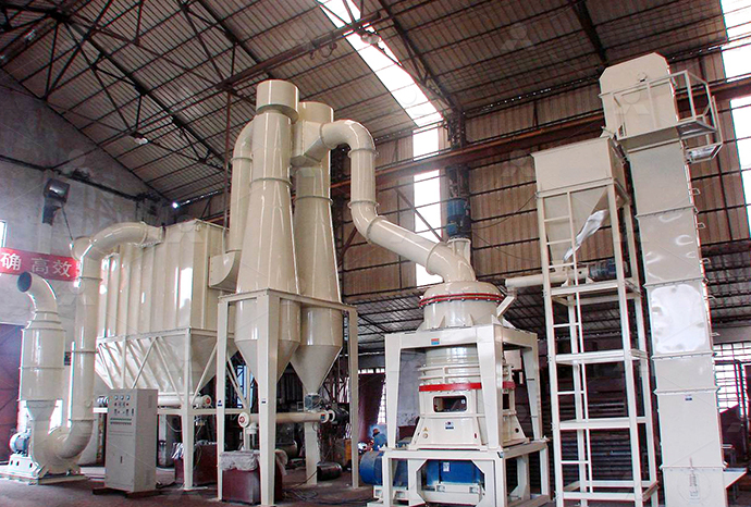
MTW European Type Trapezium Mill
Input size:30-50mm
Capacity: 3-50t/h
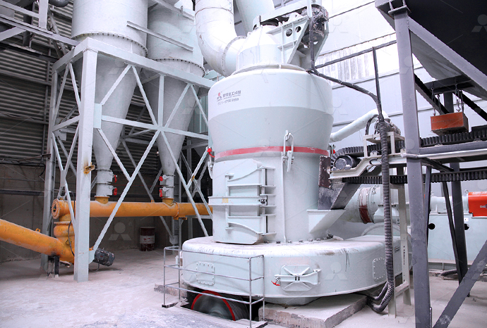
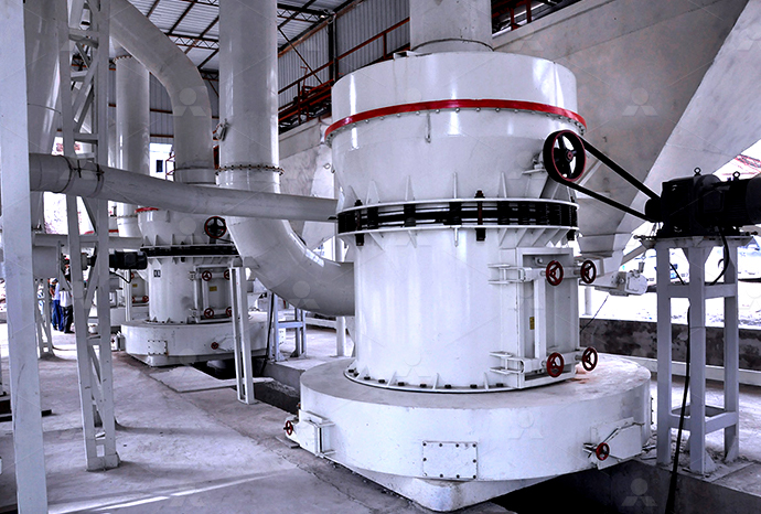
LM Vertical Roller Mill
Input size:38-65mm
Capacity: 13-70t/h
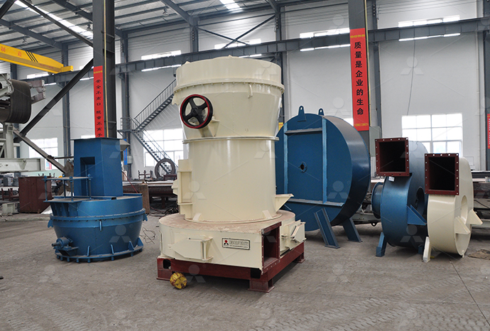
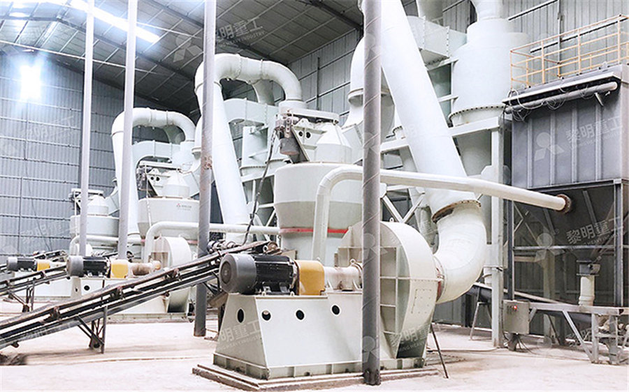
Raymond Mill
Input size:20-30mm
Capacity: 0.8-9.5t/h

Sand powder vertical mill
Input size:30-55mm
Capacity: 30-900t/h

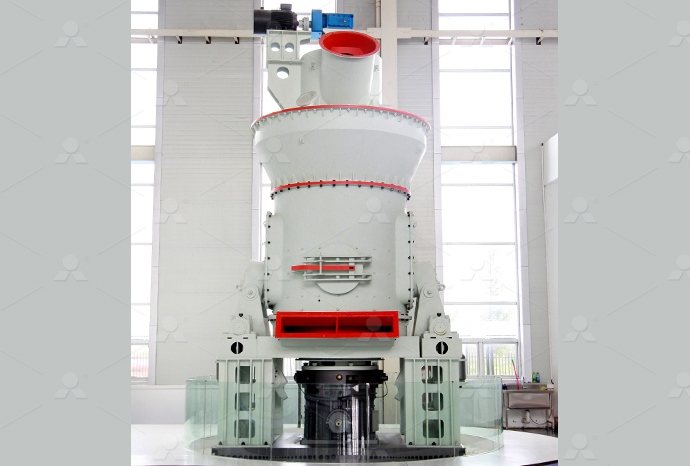
LUM series superfine vertical roller grinding mill
Input size:10-20mm
Capacity: 5-18t/h
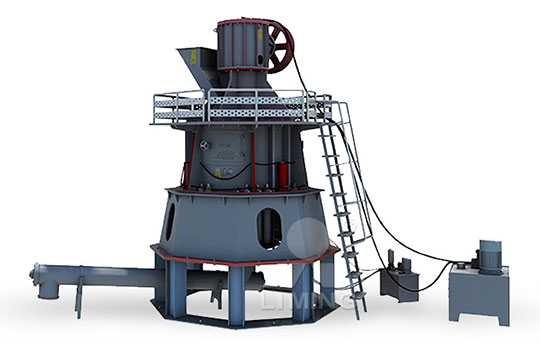
MW Micro Powder Mill
Input size:≤20mm
Capacity: 0.5-12t/h

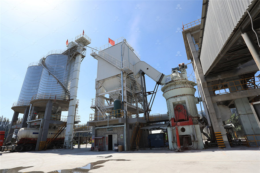
LM Vertical Slag Mill
Input size:38-65mm
Capacity: 7-100t/h

LM Vertical Coal Mill
Input size:≤50mm
Capacity: 5-100t/h
TGM Trapezium Mill
Input size:25-40mm
Capacity: 3-36t/h

MB5X Pendulum Roller Grinding Mill
Input size:25-55mm
Capacity: 4-100t/h
Straight-Through Centrifugal Mill
Input size:30-40mm
Capacity: 15-45t/h
Feeder Controller Schematic Diagram
.jpg)
VibroBlock Feeders How They Work Arthur G Russell Company
Most feeders (of current manufacture) use one of 2 standard controllers Either controller is powerful enough to operate any standard feeder They differ primarily in the manner which the Check the input voltage before switching on the controller The control is set to the voltage specified by the user at the factory Be sure to use the same voltage specified If voltage must Installation, Operation and Maintenance InstructionsNeoGCP fFD PLUS+ / Feeder controller for fire fighting Brochure (KOR) Layout (ENG) Schematic diagram (KOR) FEEDER controller > NeoGCP FD PLUS+ NeoGCP FD PLUS+ / Feeder controllerRefer to the supplied schematic and outline drawing for connections The installation of a fused safety switch or branch circuit breaker ahead of the controller is recommended Using the Installation, Operation and Maintenance Instructions
.jpg)
Feeder Protection and Control REF615 Application Manual ABB
Functional diagrams for control and interlocking145 Standard configuration H149 (a) Overall structure of the PV inverter and distribution feeder controller (b) Detailed structure of the proposed distribution feeder controllerSchematic diagram of the PV inverter and feeder Refer to the schematic and outline drawing and Instruction Operation Manual for the specific Eriez control operating your feeder Check the specifications of the power line to be certain that they Installation, Operation and Maintenance InstructionsDownload scientific diagram Closedloop schematic diagram of the distribution feeder controller from publication: Control Scheme for Phase Balancing and Reactive Power Support fromClosedloop schematic diagram of the distribution
Feeder protection and control Protection relays ABB Group
Feeder protection, or more exactly protection for overhead lines and cables, is the most commonly used type of protection The protection has to ensure that the power grid continues This section describes the specific features, functions and benefits of VR3S Recloser, PCD2000, Loop Control, VS3S Switch, SCD2000, ISD2000 and DCD2000 Tables and diagrams Feeder Automation AF2000 ABBDownload scientific diagram Schematic diagram of the PV inverter and feeder controller (a) Overall structure of the PV inverter and distribution feeder controller (b) Detailed structure of the Schematic diagram of the PV inverter and feeder 3 Pulsar® Precision Feeder Overview Figure 2 Front View of Pulsar® Precision Feeder A4 B2 A5 A6 A1 B1 A2 A3 A B 3 1 Components List The Pulsar® Precision Feeder includes these components: A Hopper, which includes: A1 Hopper lid, hinge pin, and retainer A2 HCE grid basket A3 HCE bowl A4 Junction Box A5 Front cover A6 Feeder control boxPulsar® Precision System
Basic Wiring McDonnell Miller SupplyHouse
LWCO Water Feeder Wiring 24V BURNER • 120V FEEDER 120V BURNER • 24V FEEDER Series 67 LWCO 101A Feeder 120V BURNER • 120V FEEDER 24V BURNER • 24V FEEDER These are suggested wiring diagrams but not the only solution to a particular installation They cover different combinations of controls including different control voltagesAutomatic StarDelta Starter (YΔ) Using Timer for 3Phase Induction Motor Schematic Power, Control, PLC Ladder and Wiring Diagrams How to Wire a StarDelta Starter with Electric Motors?Automatic Star Delta Starter Power, Control Wiring Diagram2024年4月19日 Diagram Components: The DOL starter wiring diagram includes a circuit breaker, contactor, and overload relay, essential for motor protection and operation Working Principle: The starter directly connects the motor to a threephase supply, utilizing a control circuit energized from two phases to manage start and stop functionsDOL Starter (Direct Online Starter): Wiring Diagram Electrical4U2020年7月19日 Related: Circuit Breaker Control Schematic Explained Wiring Diagram Wiring Diagram Explained Load Detector Relay 852×550 419 KB Load Detector Relay Wiring Diagram Example Feeder schedules are used to help identify the size and number of wires used for the incoming service and outgoing loads within a construction projectElectrical Drawings and Schematics Overview Articles TestGuy
Koi Pro Fish Feeder
Fig E Place the Fish Feeder in the bracket and feed the cable through the cable guide of the bracket Fig A Connect cables of the controller and feeder to each other Mount the controller with a screw on a wall, in a dry and splashfree location Pellet size • The Fish Feeder is suitable for pellets with a diameter between 29 mmVibratory bowl feeders are used for the actuation of sorting machines The actuation takes place by electromagnets The following schematic diagram shows the function of a vibratory bowl feeder: The drive magnet D is firmly connected with the countermass F When current passes the drive magnet, it exerts power on armature EOperating instructions Vibratory bowl feeder RNA Automation2018年3月14日 On these diagrams the three phase equipment and connections are shown with a single line, thus the basis for the diagram name Single phase equipment may have the same symbol as a three phase device but will be specifically designated with the phase to which it is connected Since three phase devices can be connected in a delta, phase to phase Single Line Diagrams and IEC 61850 Process Bus EEP2015年12月19日 A single line diagram is a simplified schematic of a multiline power distribution system, which may include threephase, threephase with neutral, singlephase with neutral, or direct current with two lines Oneline diagrams utilize a single line to represent the many components of a distribution system as seen in a schematic or wiring diagramLearn To Interpret Single Line Diagram (SLD) EEP
.jpg)
Feeder controller
NeoGCP fFD PLUS+ / Feeder controller for fire fighting Brochure (KOR) Layout (ENG) Schematic diagram (KOR) FEEDER controller > NeoGCP FD PLUS+ NeoGCP FD PLUS+ / Feeder Controller Brochure (KOR) Manual (KOR) Layout (KOR) Layout (ENG) Schematic diagram (KOR) B617, Smart Valley, 30 , Songdomiraero, Yeonsugu, Incheon, KOREA, Download scientific diagram Schematic representation of a vibratory bowl feeder [2] from publication: Reinforcement learning–based design of orienting devices for vibratory bowl feeders The Schematic representation of a vibratory bowl feeder [2]2022年7月25日 A realworld example of VFD power and control circuit diagrams for smoke extraction fan will be analyzed Inside Variable Frequency Drive (VFD) panel: Configuration, schematics and troubleshooting The article starts with Inside Variable Frequency Drive (VFD) Panel: DPU245 to REF615 PCMU 445 schematic ( en pdf Connection diagram ) DPU245 to REF615 PCMU 245 schematic ( en pdf Connection diagram ) REF601 / REJ601 22 FP1, Feeder protection and control / Feeder protection, Modbus Communication Protocol Manual ( en pdf Feeder protection and control Protection relays ABB Group
.jpg)
The essentials of designing MV/LV single line diagrams (symbols
2019年7月29日 Other requirements such as: Zone Selective Interlocking of breakers, 100% rated breakers, drawout or electrically operated breakers and key interlock schemes can be overlooked if they are not documented on a Single Line Diagram and coordinated in the specifications Finally, electrical equipment is subject to environmental issues such as wet Download scientific diagram Smart Dog Feeder Schematic from publication: Smart dog feeder design using wireless communication, MQTT and Android client Regular feeding is one of the problems in Smart Dog Feeder Schematic Download Scientific Diagram2021年6月22日 Hi, I am trying to generate schematic diagrams for electric distribution feeders The diagram needs to go from left to right and both sides with the subnetwork controller for the feeder (Circuit Breaker in a substation) Breaker needs to be the leftmost point and edges and junctions flowing rightwarFeeder Diagram and algorithm logic Esri CommunityVFD (Variable Frequency Drive) control circuit diagram is a schematic representation of the various components and connections in a VFD control system A VFD control system is used to regulate the speed and torque of an electric motor by varying the frequency and voltage supplied to VFD Control Circuit Diagram: A Comprehensive Guide
.jpg)
RODIX FEEDER CUBE FC40 PLUS SERIES MANUAL Pdf Download
Controllers FEEDER CUBE FC40 Plus Series controller pdf manual download Also for: Feeder cube fc40240plc plus, Feeder cube fc40dcplc plus, diagram A Power input should be OFF or disconnected B Rotate MAIN CONTROL DIAL on front cover to 0 or its minimum setting2021年11月30日 A singleline diagram (SLD) is a highlevel schematic diagram showing how incoming power is distributed to equipment Below is the CSA Z462 single line diagram definition: A411 SingleLine (OneLine) Diagram: A diagram which shows, by means of single lines and graphic symbols, the course of an electric circuit or system of circuits and the component What Is a Single Line Diagram How to Draw a Circuit DiagramIt's easy to install with a fourwire hookup and it's easy to operate TheTimer deer feeder timer can feed up to six times a day and times can vary Builtin batterylevel indicator Push button to reset Wiring harness included This game TheTimer Deer Feeder Timer Game Feeder TimerIt features a sleek design and intuitive controls that enhance the gaming experience To fully understand the functionality and inner workings of the controller, it can be helpful to explore the PS4 controller schematic diagram A Peek into the Ps4 Controller: A Schematic Diagram

Understanding the Pid Controller: A Visual Schematic
Why is a PID controller schematic diagram important? A PID controller schematic diagram is important because it provides a visual representation of how the controller operates It helps engineers and technicians understand the elementary diagram or a schematic diagram) is representation of the system showing it in the simplest way No attempt is made to show the various devices in their actual relative positions All control devices are shown between vertical lines which represent the source of control power, and circuits are shownGI20: Typical Wiring Diagrams Rockwell AutomationDownload scientific diagram Feeder AC and DC schematic (simplified) from publication: Redundancy Considerations in Protection and Control of Distribution Feeders Redundancy and Protection Feeder AC and DC schematic (simplified) Download Scientific DiagramDownload scientific diagram Weigh Feeder Controller Loop from publication: Modelling And Pi Tuning Using Ga For An Industrial Weigh Feeder Modelling And Pi Tuning Using Ga For An Industrial Weigh Feeder Controller Loop Download Scientific Diagram

Water Handbook Chemical Feed Systems Veolia Water
The only manual labor involved is the loading of the bin associated with the volumetric screw feeder CHEMICAL CONTROL SYSTEMS Figure 3515 is a schematic of a computerized cooling water chemical feed, Flow diagram of constantpressure feed using a backpressure regulator and pump XMake sure that the connected load of the vibratory bowl feeder, control unit and power supply corresponds to each other Notice The following schematic diagram shows the function of a vibratory bowl feeder: RheinNadel Automation GmbH 6 14042014 VTBASRC160800GBOperating instructions Vibratory bowl feederThe control is designed to operate from a singlephase line source It must be wired in strict accordance with the wiring diagram supplied inside the control box Control illustration, wiring schematics, and parts lists are supplied on page 6 Power supply voltage and frequency must be that which is stamped on the equipment nameplateSyntron EB00 Vibratory Parts Feeder GENERAL MANUAL Homer 2017年2月3日 Legal Requirements – As required by the NEC, NFPA 101, NFPA 99 and other local, state, and federal codes and requirements These are concerned with the safety of human life, protection of the environment, etc Economic Considerations – Continuous process applications often require a continuous source of electrical power to avoid significant economic Single line diagrams of emergency and standby power systems
.jpg)
SCADA Application for Control and Monitoring of Vibratory Feeder
Schematic diagram of the energy converter and the corresponding PWM control circuit are shown in Figure 2 The waveforms of typical signals are shown in Figure 32024年4月12日 In a Generac Home Standby Generator installation, control wires play an essential role in allowing proper communication between the generator, transfer switch, and utility power source The N1/N2, T1, 23/194, What is the layout of the control wires and what do Bay controller – Schematic diagram Bay controller – Signal list: • Single‐line diagram of the associated bay/feeder • BIO cards identifications • Slots identifications • Object identifications (HV apparatus, signal, function) • Signals texts • Signals types • Signals positions • Specific reference on schematic diagramSubstation Automation Systems: Design and ImplementationDisclaimer The data, examples and diagrams in this manual are included solely for the concept or product description and are not to be deemed as a statement of guaranteedFeeder Protection and Control REF615 Application Manual ABB
Understanding VFD Schematic Diagram and Control
A VFD schematic diagram may also include additional components and subsystems, depending on the specific application These can include braking resistors, input reactors, output reactors, and various control and feedback devices Each component and connection in the schematic diagram plays a crucial role in the overall operation of the VFD systemIn conclusion, the Trip Hopper Feeder wiring diagram is an invaluable tool for livestock farmers It provides a comprehensive visual guide to the electrical connections that power and control the feeder By understanding and following this diagram, farmers can set up the feeder efficiently and troubleshoot any issues that may ariseA Comprehensive Guide to Trip Hopper Feeder Wiring DiagramsDiagrams Chapter 3 Material taken from Chapter 3 of Electric Motor Controls, G Rockis, 2001 OneLine Diagrams Oneline diagram – a diagram that uses single lines and graphic symbols to indicate the path and components of an electrical circuit Oneline diagrams are used when information about a circuit is requiredElectrical Symbols and Line Diagrams University of FloridaDownload scientific diagram Schematic diagram of system with PID controller from publication: Analysis of Tracking Performance in Machine Tools for Disturbance Forces Compensation using Sliding Schematic diagram of system with PID controller
.jpg)
Detailed Wiring Diagram for Dali Lighting Control System
Functionality: Individual Control: The Dali lighting control system allows for individual control of each Dali device, allowing users to adjust brightness, switch on/off, and set different lighting scenes Zonal Control: Multiple Dali devices can be grouped into zones, enabling users to control the lighting in specific areas or rooms Daylight Harvesting: Dali sensors can be integrated into 2023年7月31日 The parallel feeder system is used when a high power demand necessitates multiple feeders to supply power to the loads in parallel This configuration ensures adequate power supply and load sharing Configuration The SingleLine Diagram of a parallel feeder system includes two or more feeders running in parallel from the power source to the loadsInterpretation and Configuration of SingleLine Diagram Study