


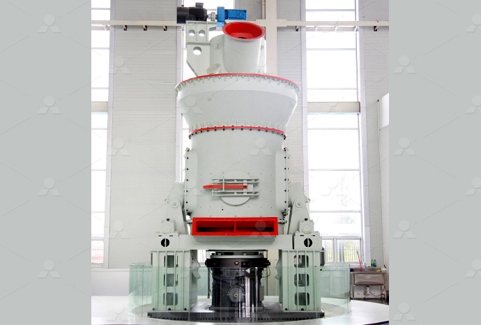
MTW European Type Trapezium Mill
Input size:30-50mm
Capacity: 3-50t/h
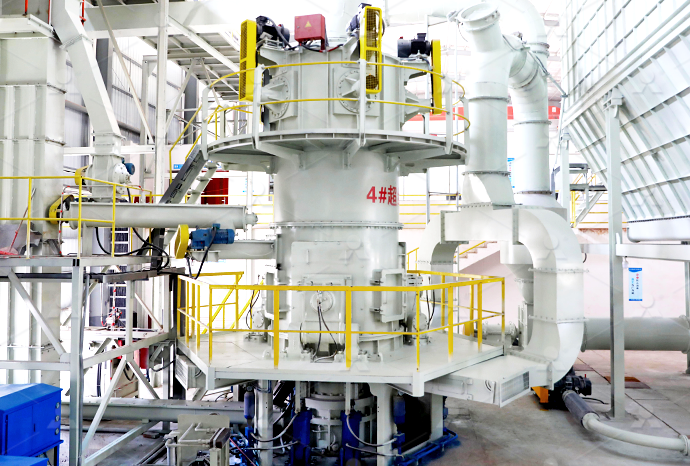
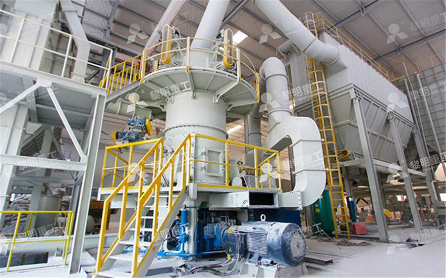
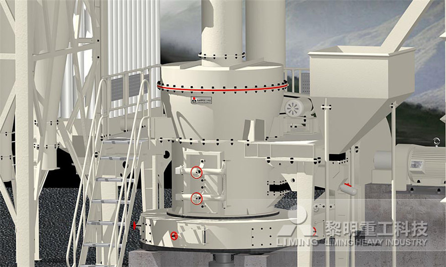
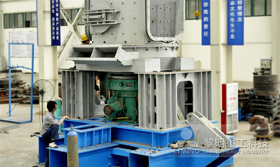
LM Vertical Roller Mill
Input size:38-65mm
Capacity: 13-70t/h
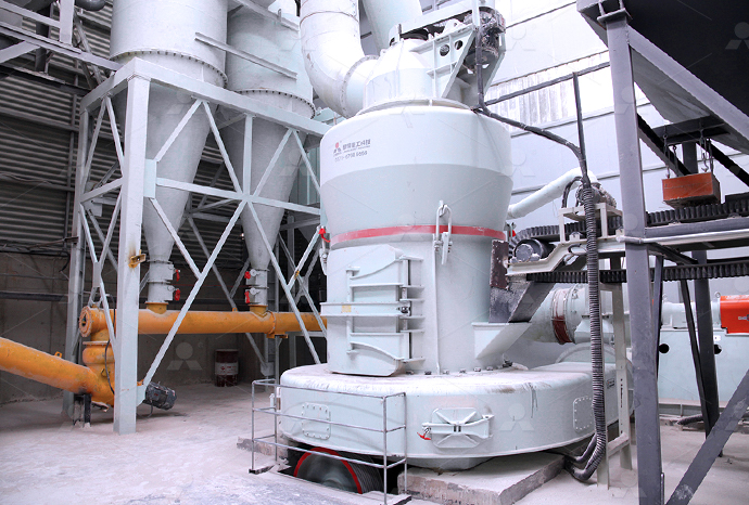
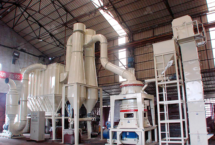
Raymond Mill
Input size:20-30mm
Capacity: 0.8-9.5t/h
Sand powder vertical mill
Input size:30-55mm
Capacity: 30-900t/h
LUM series superfine vertical roller grinding mill
Input size:10-20mm
Capacity: 5-18t/h
MW Micro Powder Mill
Input size:≤20mm
Capacity: 0.5-12t/h

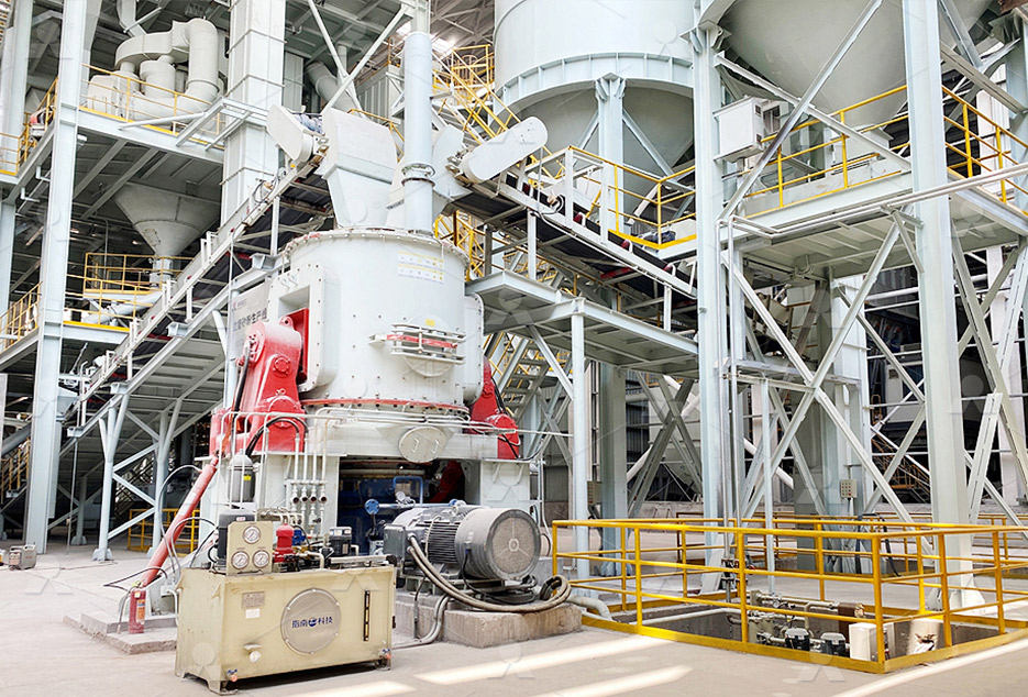
LM Vertical Slag Mill
Input size:38-65mm
Capacity: 7-100t/h

LM Vertical Coal Mill
Input size:≤50mm
Capacity: 5-100t/h
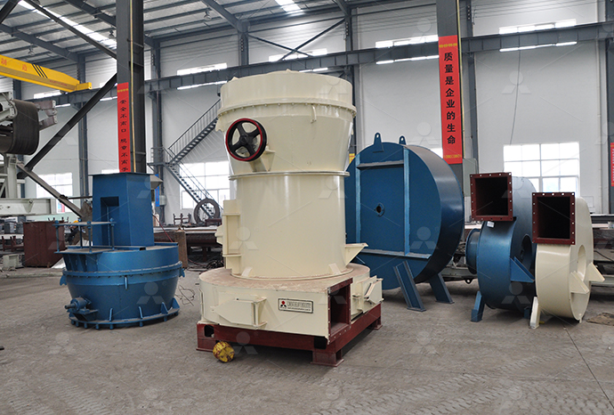
TGM Trapezium Mill
Input size:25-40mm
Capacity: 3-36t/h

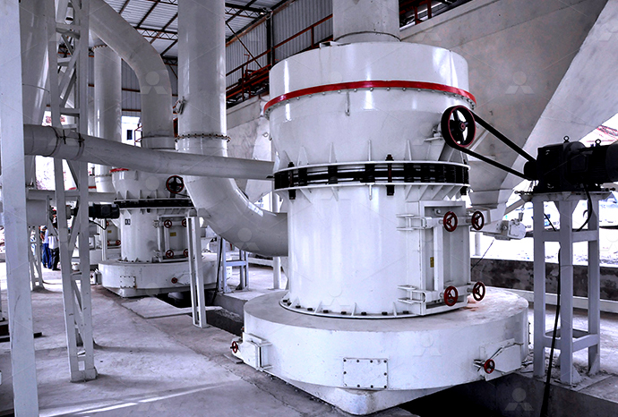
MB5X Pendulum Roller Grinding Mill
Input size:25-55mm
Capacity: 4-100t/h
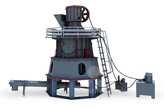
Straight-Through Centrifugal Mill
Input size:30-40mm
Capacity: 15-45t/h
Detailed explanation of Dongcheng powder selection machine circuit diagram
.jpg)
DONGCHENG DCJF22 OPERATION INSTRUCTIONS MANUAL Pdf
View and Download Dongcheng DCJF22 operation instructions manual online DCJF22 cutoff machines pdf manual download Also for: Adjf22, Kdjf22202310 DongCheng Product Catalogue DOWNLOAD DATA DOWNLOAD DONGCHENG2020年12月15日 The text provides a holistic understanding of machining processes and machines in manufacturing; it enables critical thinking through mathematical modeling and (PDF) Machining Processes and Machines: FundamentalsPowderProcess is a free online handbook giving explanations, design methods and operational tips on the most common unit operations and equipment found in Industries powderprocess Engineering resources for powder
.jpg)
Powder Selection SpringerLink
2016年4月28日 In this section we define the needed powder characteristics and identify the best powder fabrication routes to deliver that powder To understand and specify a powder requires 2023年8月2日 The integrated circuit design and manufacturing process involves the design, fabrication, testing, and packaging of an IC There are several steps in the IC design and IC Design and Manufacturing Process CadenceFigure 1611 A 450 kN (50ton) hydraulic press for compaction of powder metallurgy components This press has the capability to actuate multiple levels to produce complex PM Powder Metallurgy PDFdrawio is free online diagram software You can use it as a flowchart maker, network diagram software, to create UML online, as an ER diagram tool, to design database schema, to build Flowchart Maker Online Diagram Software
Understanding CNC Machine Circuit Diagrams and the Importance
In this blog post, we will delve into the intricacies of CNC machine circuit diagrams and explore the importance of having PDF documentation for these diagrams Section 1: The Basics of A washing machine block diagram explanation PDF provides a detailed overview of the different components and functions of a washing machine In this document, each major component of the washing machine is explained in The Ultimate Guide to Understanding Washing Hydraulic Circuit Diagram with Explanation In a hydraulic system, a circuit diagram is a graphical representation of the different components and connections that make up the system It shows how the fluid flows through the system and how the different components interact with each other to perform specific tasksUnderstanding Hydraulic Circuit Diagrams: Explained in Detail2018年6月12日 It outlines how elements such as the welding machine, power supply, heating element, and other components interact with each other A welding machine circuit diagram is the first step toward creating a seamless Welding Machine Circuit Diagram Wiring Digital
.jpg)
Pin diagram of 8085 microprocessor GeeksforGeeks
2023年5月7日 Advantages of the 8085 microprocessor pin diagram: The pin diagram is easy to understand and remember because of its logical and systematic arrangement It has a simple structure with fewer pins compared to other microprocessors, making it easy to design and implement in electronic circuitsThe DC shunt motor circuit diagram is shown below, and the flow of current and voltage being supplied to the motor from the supply can be given by Itotal E DC Shunt Motor Circuit Diagram In case of the shunt wound DC motor, this current supply will divide into two ways like Ia, Ish, where ‘Ia’ will supply throughout the ‘Ra’ resistance armature windingDC Shunt Motor : Construction, Circuit Diagram, and Its2017年12月12日 These detailed diagrams help to explain even the most complex mechanics of a machine, making them the perfect resource for both experienced professionals and aspiring hobbyists Along with providing insight into the inner workings of a machine, a lathe machine schematic diagram also allows individuals to get a better understanding of proper setup and Lathe Machine Schematic Diagram275: Draw the state diagram of the circuit described below, with detailed explanations: You are to design the main logic of a simple automatic vending machine The soda cans inside the machine cost 25, and the machine accepts only nickels, dimes, and quarters An electromechanical subsystem accepts the coins sequentially275: Draw the state diagram of the circuit described Chegg
.jpg)
CNC Machine Block Diagram: Systems Components (Parts) of
2023年9月26日 Main Components (Parts) of CNC Machine A CNC (Computer Numerical Control) machine is a sophisticated piece of equipment used in manufacturing and machining processes to automate and control the movement of tools and workpieces with a high degree of precision CNC Machine Block Diagram Now let’s break down the main components of a CNC Series Wound DC Machine; Shunt Wound DC Machine; Compound Wound DC Machine; Series DC Machine In this type of DC machine, the field winding is connected in series with the armature winding Because of the series connection, the entire load current (armature current) will pass from the field winding And this current is highDC Machine – Construction, Working, Types and ApplicationsQuestion: 275: Draw the state diagram of the circuit described below, with detailed explanations: You are to design the main logic of a simple automatic vending machine The soda cans inside the machine cost ₫25, and the machine accepts only nickels, dimes, and quarters An electromechanical subsystem accepts the coins sequentiallySolved 275: Draw the state diagram of the circuit described2024年3月26日 6 Printed Circuit Board Printed circuit board or PCB or IC board or control board, is an electronic board in an air conditioner used to control the operation of almost all of the components including the compressor, fans, Air Conditioner Working Principle Simple
.jpg)
Understanding Solar Panel Diagrams: A Detailed
Solar Panel Diagram with Explanation PDF A solar panel diagram with explanation PDF provides a detailed visual representation of how solar panels work and generate electricity from sunlight The diagram typically includes the 276: Draw the state diagram of the circuit described below, with detailed explanations: A detection circuit has two inputs, xi and x2, such that an output z will become 1 as soon as 4 consecutive input pulses are received and the 4bit sequence contained at least two xı pulses Assume the sequences consisting of xi and x2 may not overlapSolved 276: Draw the state diagram of the circuit described CheggThe circuit diagram assumes that the light bulbs are connected in series However, it’s important to note that they can also be connected in parallel or in different combinations This example highlights the two common types of connections found in electric circuits: series and parallelUnderstanding Circuit Diagrams Components, Reading Guide 2017年12月8日 Ultimately, understanding the Bosch washing machine circuit diagram can save time and money when it comes to maintaining and repairing the machine Whether you’re a DIY enthusiast, a professional repairman, or simply a curious owner, a reliable and detailed diagram can help you stay informed and protect against costly repair billsBosch Washing Machine Circuit Diagram Wiring Digital and
.jpg)
555 Timer IC – Working Principle, Block Diagram, Circuit Schematics
In this tutorial we will learn how the 555 Timer works, one of the most popular and widely used ICs of all time It is a highly stable integrated circuit that can produce accurate time delays and oscillations The 555 Timer has three operating modes, bistable, monostable and astable mode2020年6月4日 This project can also be made fully automatic if you replace the switch with the ultrasonic sensor or PIR sensors or Laser etc There are different types of the sensors available in the market So first let’s start with the circuit diagram Circuit Diagram of the PLC based Staircase Light Control System:PLC Ladder Logic Programming Examples with detailed explanationFlowchart Maker and Online Diagram Software drawio is free online diagram software You can use it as a flowchart maker, network diagram software, to create UML online, as an ER diagram tool, to design database schema, to build BPMN online, as a circuit diagram maker, and more drawio can import vsdx, Gliffy™ and Lucidchart™ files Flowchart Maker Online Diagram Software2010年3月2日 This report presents a detailed explanation of the Design requirements of Electronic control Unit (ECU) for Engine Management Due to the regulations demanding lower emissions, together with the need for better performance, fuel economy, continuous diagnosis, Electronic systems form an inevitable part of Engine managementDesign of Electronic Control Unit (ECU) for Automobiles
.jpg)
Understanding Schematics Technical Articles All About Circuits
2019年7月22日 That idea is then defined, with words and diagrams, in a specification Anyone can take an idea this far, but the next step requires a fundamental understanding of circuit schematics Circuit schematics are the bridge between conceptual electrical design and physical realization of a printed circuit board assembly, or PCBA2018年8月5日 Lg Automatic Washing Machine Wiring Diagram Fully4world Washing Machine With An Improved Rinsing Liquid Inlet Circuit Diagram Schematic And Image 03 Washing Machine Wiring Diagram Pour Android Washing Machine Wiring Diagram And Schematics2024年1月15日 Sidebyside comparison of the wiring diagram (drawing), the actual device, and the circuit schematic of the output circuits (MOSFET and Zener diode visible) Image used courtesy of the author Many devices exist in both Electrical Drawings, Schematics, and Wiring Diagrams: The Piping and Instrumentation Diagram (PID) is vital in this domain With this article, we will explore what is PID, its significance across diverse industries, the symbols employed, and a comprehensive guide on crafting themDetailed PID Guide for Industrial Processes Rishabh
Mealy Moore Machine KFUPM
To make sure that machine gets resetted to a valid state, we use a ‘Reset’ signal The logic diagram for this state machine is shown in Figure 5 Note that negative edge triggered flipflops are used Figure 5: Mealy State Machine Circuit Implementation Timing Diagram for the circuit is shown in Figure 62023年6月18日 Key learnings: Circuit Breaker Definition: A circuit breaker is a manually or automatically operated electrical switch designed to protect and control power systems by interrupting fault currents; How Circuit Breakers Work: By detecting faults like overloads or short circuits, circuit breakers interrupt the current flow, activate arc quenching methods, and can be Circuit Breaker: What it is And How it Works Electrical4U2019年9月2日 12V SMPS Circuit Diagram and Explanation The below circuit is slightly modified to suit our project Before going straight into building the prototype part, let’s explore the 12v SMPS circuit diagram and its operation The circuit has the following sections Input surge and SMPS fault protection; ACDC conversion; PI filter12V 1A SMPS Power Supply Circuit Design on PCBBlock Diagram of CPU Let's delve into the sequential breakdown of data flow within the block diagram of the CPU: Commencing with the input unit, data provided by the user is initially received and subsequently converted into binary format for computer comprehension; The processed information is then directed to the memory unit, where it undergoes storage and Block Diagram of CPU: Detailed Analysis of All Components
Understanding the Basics: CNC Machine Circuit Diagram Explained
The circuit diagram provides a blueprint for technicians and engineers to understand how the machine functions, troubleshoot any issues, and make modifications or upgrades as necessary In a CNC machine, the circuit diagram includes various components such as power supplies, motors, drivers, sensors, and the controller2023年4月21日 Pin diagram of 8085 microprocessor is as given below: 1 Address Bus and Data Bus: The address bus is a group of sixteen lines ie A0A15 The address bus is unidirectional, ie, bits flow in one direction from the microprocessor unit to the peripheral devices and uses the high order address bus 2Pin diagram of 8051 Microcontroller GeeksforGeeks2023年5月11日 Transformer is the simplest device that is used to transfer electrical energy from one alternatingcurrent circuit to another circuit or multiple circuits, through the process of electromagnetic inductionA transformer works on the principle of electromagnetic induction to step up or step down voltage Transformer either increases AC voltage (Stepup transformer) Transformer Definition, Types, Working Principle, EquationsThe circuit diagram maker offers an infinite workspace where you can expand your diagram in all directions Meanwhile, the grids intuitively snap elements into alignment Speed up your work with keyboard shortcuts, like typing “L” to add Free Circuit Diagram Maker: Draw a circuit diagram
.jpg)
What is JK Flip Flop? Circuit Diagram Truth Table
The circuit diagram of the JK Flip Flop is shown in the figure below: The S and R inputs of the RS bistable have been replaced by the two inputs called the J and K input respectively Here J = S and K = R The twoinput AND gates of the RS Download scientific diagram Circuit Diagram of CNC machine from publication: Design and Implementation of lowcost 2D plotter Computer Numeric Control (CNC) Machine CNC Machining, Computer and Circuit Diagram of CNC machine Download Manual Starters Recalling the equivalent circuit of a DC motor, shown in Figure 1, there is no counter EMF (E a) when the motor is at rest Thus, when the voltage is applied to the terminals, all of the voltage drops will appear across the armature resistance, R a Because R a is designed to be small, applying full voltage to it could result in current several times the rated current of DC Motor Starter: Types, Circuit Diagram Electrical AcademiaComparison of pictorial and schematic styles of circuit diagrams Common schematic diagram symbols (US symbols) The circuit diagram for a fourbit TTL counter, a type of state machine A circuit diagram (or: wiring diagram, electrical diagram, elementary diagram, electronic schematic) is a graphical representation of an electrical circuitA pictorial circuit diagram uses simple Circuit diagram Wikipedia
.jpg)
Electric circuit Diagrams Examples Britannica
2024年10月23日 Electric circuits are classified in several ways A directcurrent circuit carries current that flows only in one direction An alternatingcurrent circuit carries current that pulsates back and forth many times each second, as in most household circuits (For a moredetailed discussion of direct and alternatingcurrent circuits, see electricity: Direct electric current and The circuit consist basically of, a ZCS partial series resonant DCDC converter, a dynamic power compensator given by a bidirectional converter, and a voltage source fullbridge invertershows a detailed circuit diagram of the UPS reported in [6] The Before jumping into the inverter circuit diagram, it is necessary to know the logical symbol of the power inverter In the electronics or logic design subject, the inverter is also known as the NOT gate, which does nothing but logical negationElaborating more, the inverter or NOT gate makes the high a low and the low a highInverter Circuit Diagram: A Complete Tutorial EdrawMax2019年10月7日 After that, an American inventor namely “Thomas Davenport” was invented another commutator type DC machine and afterward, AC machines are invented This machine is used to control the devices which operate using alternating current A DC machine is used to operate the devices which use unidirectional currentDC Machine : Construction, Working Its Applications
.jpg)
Types of Electrical Drawings and Wiring Circuit Diagrams
Different Types of Electrical Wiring Circuit Diagrams and Drawings In Electrical and Electronics Engineering, we use different types of drawings or diagrams to represent a certain electrical system or circuitThese electrical circuits are represented by lines to represent wires and symbols or icons to represent electrical and electronic componentsIt helps in better understanding the