


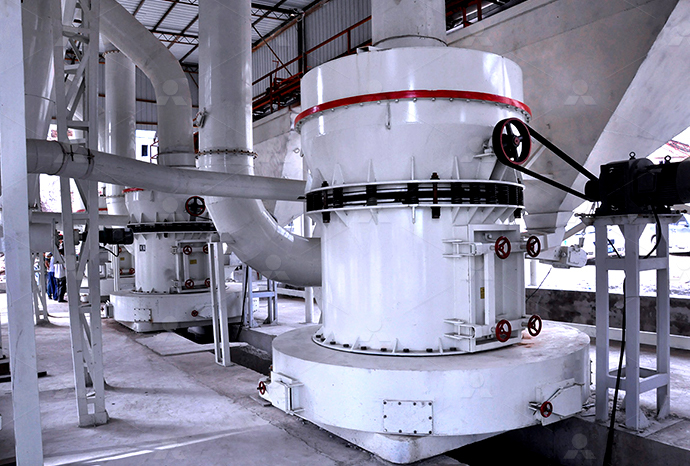
MTW European Type Trapezium Mill
Input size:30-50mm
Capacity: 3-50t/h
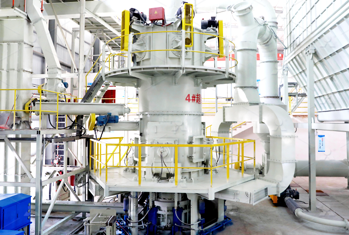
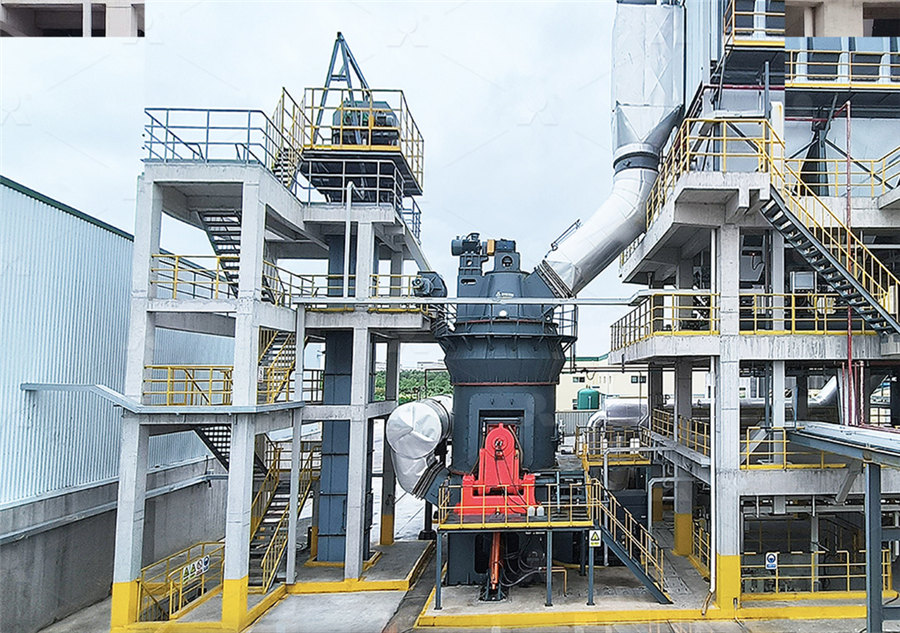
LM Vertical Roller Mill
Input size:38-65mm
Capacity: 13-70t/h
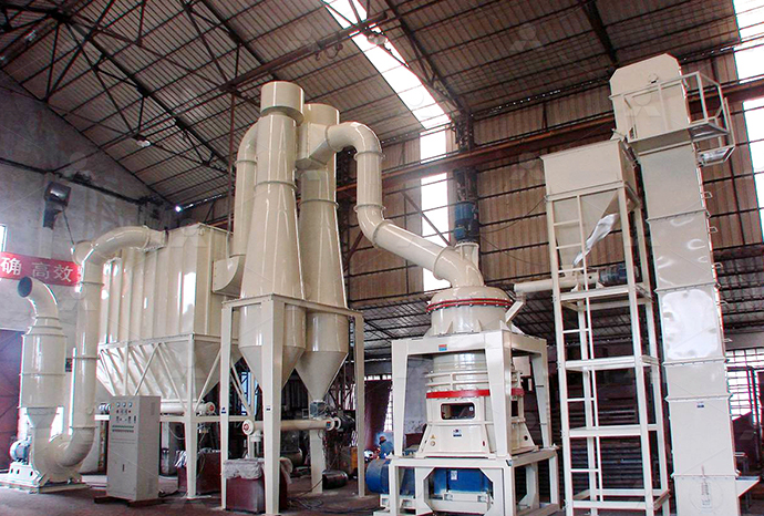
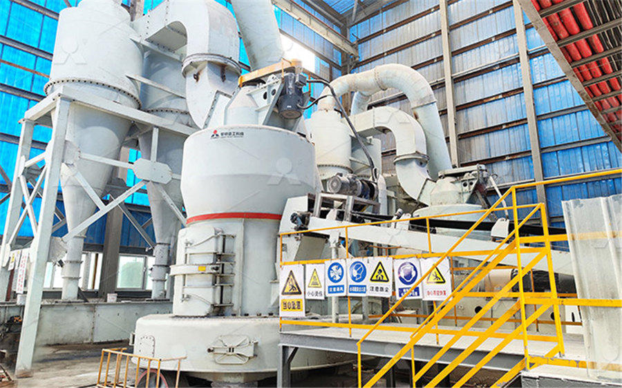
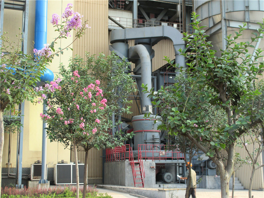
Raymond Mill
Input size:20-30mm
Capacity: 0.8-9.5t/h
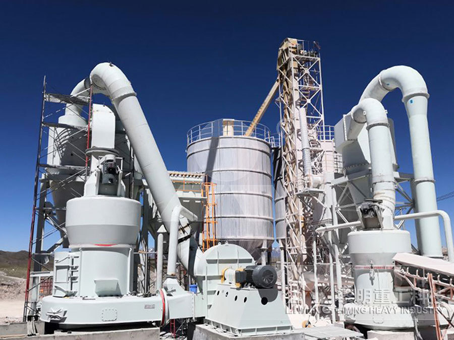
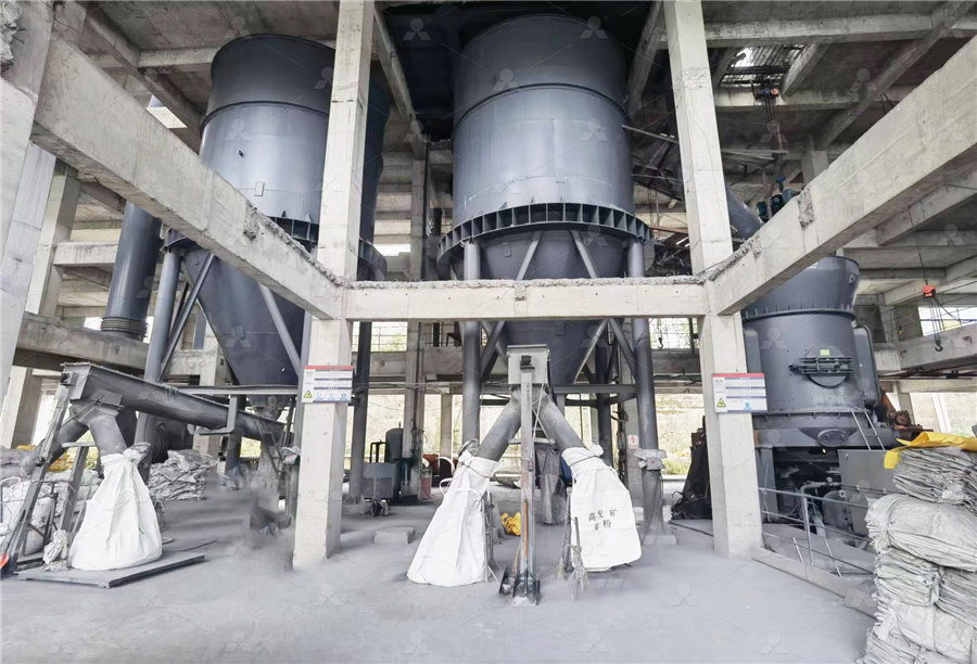
Sand powder vertical mill
Input size:30-55mm
Capacity: 30-900t/h
LUM series superfine vertical roller grinding mill
Input size:10-20mm
Capacity: 5-18t/h
MW Micro Powder Mill
Input size:≤20mm
Capacity: 0.5-12t/h

LM Vertical Slag Mill
Input size:38-65mm
Capacity: 7-100t/h
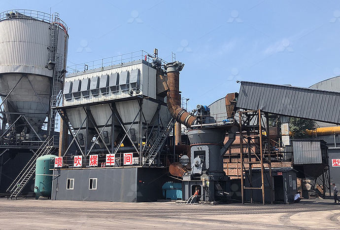
LM Vertical Coal Mill
Input size:≤50mm
Capacity: 5-100t/h
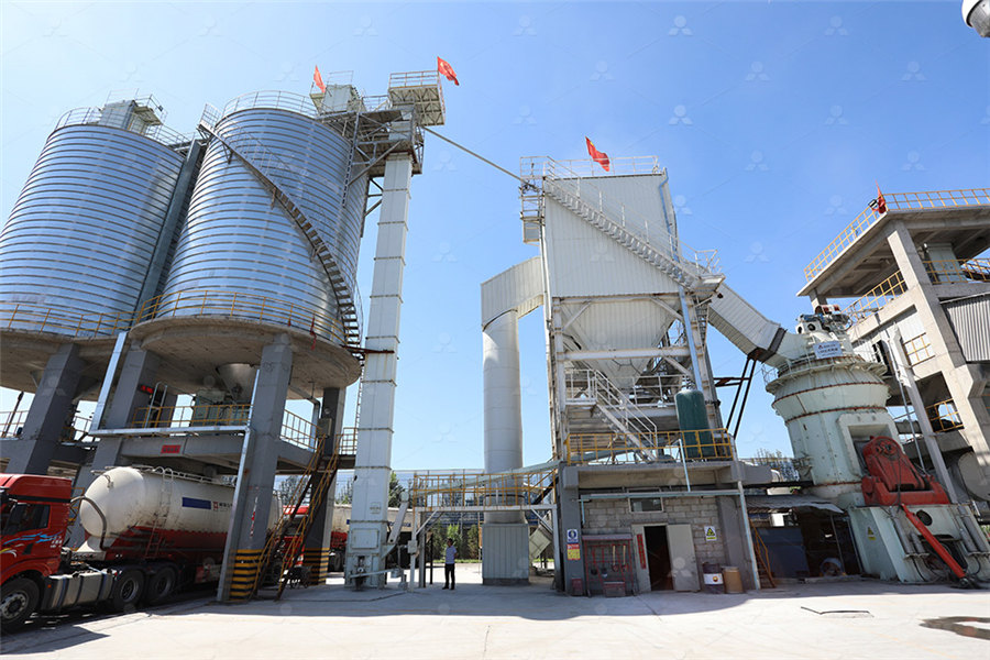
TGM Trapezium Mill
Input size:25-40mm
Capacity: 3-36t/h

MB5X Pendulum Roller Grinding Mill
Input size:25-55mm
Capacity: 4-100t/h
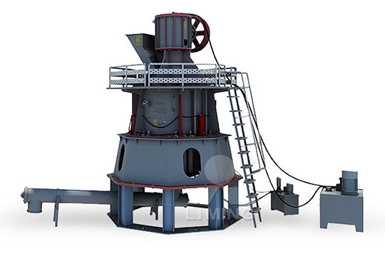
Straight-Through Centrifugal Mill
Input size:30-40mm
Capacity: 15-45t/h
cycloidal speed increaser
Using a Speed Reducer as a Speed Increaser RJ Link
Spur and helical gear reducers are the best candidates for use as a speed increaser Generally a helical or spur gear speed reducer may be used as a speed increaser within the same speed For example, a 4:1 ratio helical gear 2024年1月19日 The cycloid reducer’s tooth profile error and correction are critical parameters that affect the cycloidal reducer, and the measurement of the whole tooth profile error through radial tracking mode in polar coordinates can QuasiStatic Force Analysis and Tooth Profile Dynamics analysis of cycloidal speed reducers with pinwheel and nonpinwheel designsChiuFan Hsieh Google Scholar2021年10月1日 In chapters 2 and 3, a cycloid reducer design method using an epitrochoidal curve is presented, and in chapter 4, the characteristics of the gear profile according to the Geometry design and dynamic analysis of a modified cycloid
Features of a cycloid speed increaser with double satellite gear for
2009年4月1日 objective, a cycloid speed reducer produced by Onvio Company is considered and analyzed as speed increaser, for which th e synthesis of the teeth numbers is madeThe gears of the speed increaser gearboxes can be with cylindrical teeth or cylindrical helical teeth We recommend cylindrical teeth when the peripheral speeds are low and the axial General aspects of speed increaser gearboxes ResearchGate2019年1月14日 That’s why the gearbox is called a cycloidal drive Since cycloidal drives are used to reduce the speed, they are also referred to as cycloidal speed reducers The construction of the geometry of the cycloidal How does a cycloidal drive work? tecscience2019年11月25日 We developed a highefficiency compact cycloidal reducer for legged robots that uses needle roller bearings in all parts where contact occurs during the power transfer Development of a Lightweight and Highefficiency Compact
Traditional versus improved designs for cycloidal speed reducers
2015年4月1日 Hence, this study constructs an analytic model of system dynamics in a cycloid reducer with a small tooth difference Specifically, taking a transmission ratio of 17 as an High Reduction Ratios: Cycloidal gearboxes are capable of providing very high reduction ratios in a single stage, often ranging from 30:1 to over 100:1, and even higher in multistage configurations This is significantly higher than what is typically achievable with other types of gearboxes in a single stage, making them ideal for applications requiring substantial speed Cycloidal Gearboxes Sumitomo Drivetorque that it is able to deliver Enter the Cycloidal type of speed reducer The cycloidal reducer is a completely unique type of unique features will be verified by simulating part movements through dynamic analysis and observing/analyzing forces in the finite element analysis environment using dedicated 3D modeling softwareThe Dynamic Simulation and Analysis of a Cycloidal Speed ReducerPlanetary speed increaser gearbox is a versatile industrial product which can reduce the speed of the motor and in crease the output torque Planetary speed increaser gearbox can be used as supporting parts for lifting, mining, Speed increaser gearbox
.jpg)
CNC Machined vs 3D Printed Cycloidal Drive – Designing Testing
Cycloidal Drive Overview In my previous video I already explained in details what is cycloidal drive and how it works, so I would suggest checking that video out in case you are not familiar with cycloidal driversReal quick, a cycloidal driver is a unique type of gearbox, or speed reducer which provides very high reduction ratio with a compact but robust designSpur and helical gear reducers are the best candidates for use as a speed increaser Generally, a helical or spur gear speed reducer may be used as a speed increaser within the same speed and power range for which it is rated as a speed reducer For example, a 4:1 ratio, helical gear speed reducer rated at 5 HP, 1750 RPM input can be used as a A Brief Discussion of Speed Increasers2019年3月22日 The cycloidal speed reducer is used in industry universally In order to know the influence of the design parameters on the reducer performance, this study proposes a prediction method which cannot only estimate the stability but also forecast the power loss to identify the performance differences of various designs The design of reducers in this paper follows non Performance prediction method of cycloidal speed reducers2022年1月1日 Traditional cycloidal speed reducers (with two cycloid discs per one stage, mutually turned by an angle of 180°) are well known for their remarkable dynamic stabilityA New ThreeStage Gearbox Concept for High Reduction
A New Design of a TwoStage Cycloidal Speed Reducer
2011年8月1日 A traditional twostage cycloidal speed reducer is obtained by the Find, read and cite all the research you need on ResearchGate Home Physiological Processes2023年3月1日 Traditional cycloidal speed reducers (with two cycloid discs per one stage, mutually turned by an angle of 180°) are well known for their remarkable dynamic stabilityA new threestage gearbox concept for high reduction ratios: Use The influence of the cycloid disc bearing type on the cycloidal speed reducer efficiency Milan Vasic1, Mirko Blagojevic1, Miloš Matejic1, *, and Ileana Ioana Cofaru2 1University of Kragujevac, Faculty of Engineering, 34000 Kragujevac, Sestre Janjic 6, Serbia 2"Lucian Blaga" University of Sibiu, Computer Science Electrical Engineering Department,The influence of the cycloid disc bearing type on the cycloidal speed design If the twostage cycloidal speed reducer of the new design is compared to the onestage cycloidal speed reducer with the same transmission ratio, input power, and input speed, the following can be concluded: • The newly designed twostage cycloidal speed reducer has significantly fewer rollers than the onestage cycloidal speed reducerA New Design of a TwoStage Cycloidal Speed Reducer
.jpg)
INFLUENCE OF THE FRICTION ON THE CYCLOIDAL SPEED
221 K const sin(j j F = β +β) (10) In case when all the power losses in cycloidal speed reducer are neglected, drive torque of one cycloid disk T 1 is calculated on the basis of the expression:2020年12月6日 CDs are acknowledged to provide high speed ratio in a single stage (Gorla et al, 2008; Blagojevic et al, 2014) By adopting a cycloidal profile, it is possible to generate a planetarycoupled planetary gear and a ring profile, Redesigning the cycloidal drive for innovative 2021年6月4日 Traditional cycloidal speed reducers (with two cycloid discs per one stage, mutually turned by an angle of 180°) are well known for their remarkable dynamic stabilityThe influence of the cycloid disc bearing type on the cycloidal speed The speed increaser of the machine tool spindle is referred to as speed increaser or speed increase also called speed increase tool holder The mechanical speed increaser is directly installed in the taper hole of the main shaft of the machine tool through a shank (BT DIN, etc), and is tightened by a pulling nail mechanism, which is almost the same as the ordinary tool The difference between a gear speed reducer and a speed increaser
A Combined AnalyticalNumerical Approach to Evaluate the
2023年8月4日 This system is used in a variety of sectors eg, robot systems, aviation, CNC machines and it represents a rising trend in the automotive sector with regard to electric motors [1, 2]Considering Fig 1 the kinematics of the system can be described as follow The rotation is driven by the eccentric input shaft (green) on which a cycloidal disk (blue) is seated my means Planetary speed increaser gearbox is a versatile industrial product which can reduce the speed of the motor and in crease the output torque Planetary speed increaser gearbox can be used as supporting parts for lifting, mining, transportation, construction and other industries Series: number of sets of planetary gearsSpeed increaser gearboxCycloidal speed reducers VIEW PRODUCTS Speed increaser VIEW PRODUCTS Gearmotors VIEW PRODUCTS Write to us and we will contact you as soon as posible acotec@tecnongroup find us Martina Céspedes 2869, B1607 Villa Adelina, Buenos Aires, Argentina contact us Tel +5411 4766 1500Speed reducers and gearmotors TecnonTraditional cycloidal speed reducers (with two cycloid discs per one stage, mutually turned by an angle of 180) are well known for their remarkable dynamic ° stability This paper analyses dynamic behaviour of a twostage cycloidal speed reducer of a new concept, in which only one cycloid disc is used for each stage in order to Dynamic Behaviour of a TwoStage Cycloidal Speed Reducer of a
.jpg)
Dynamic Analysis of a Cycloidal Gearbox Using Finite Element Method
2013年8月10日 A New Design of a TwoStage Cycloidal Speed Reducer Journal of Mechanical Design, 2011 133(8): p (7 pp) 2 Gorla, C, et al, “Theoretical and experimental analysis of a cycloidal speed reducer” Journal of Mechanical Design, Transactions of the ASME, 2008 130(11): p 2023年3月1日 Based on the data from Table 1, it can be concluded that the approximate values of the gear ratios of cycloidal speed reducers with classic concept are 3–119 for onestage, 81–7569 for twostage, and 990– for threestage gearboxes On the other hand, A new threestage gearbox concept for high reduction ratios: Use cycloidal speed reducers belong to the new generation of mechanical gears cy cloidal speed reducers are increasingly used in modern engineering due to their good performances Friction exists at all points of contact between the moving elements of cycloidal speed reducers, as one of the main causes of power losses in power transmission In this paper, the friction of the INFLUENCE OF THE FRICTION ON THE CYCLOIDAL SPEED 2020年9月30日 A cycloidal gear is mainly used to increase or decrease the speed We are going to use it to decrease the speed while increasing the accuracy of the projectileDesign, Analysis and Simulation of Compact Cycloidal Drive

(PDF) INFLUENCE OF THE FRICTION ON THE CYCLOIDAL SPEED
Journal of the Balkan Tribological Association Vol 18, No 2, 217–227 (2012) Friction in cycloidal speed reducers INFLUENCE OF THE FRICTION ON THE CYCLOIDAL SPEED REDUCER EFFICIENCY M BLAGOJEVIca*, M KOcIcb, N MARJANOVIca, B STOJANOVIca, Z dORdEVIca, L IVANOVIca, V MARJANOVIca a Faculty of Mechanical Engineering, 2023年3月1日 For instance, with a single stage of an harmonic drive it is possible to reach GRs ranging from 50 to 160 [6], [7]GRs ranging from 30 to 100 can be achieved through a single stage of a cycloidal drive [6], [7]To achieve such GRs with planetary gearboxes, architectures involving multiple stages have to be exploited [8]Therefore, to reach GR greater than 160 multiple A new threestage gearbox concept for high reduction ratios: Use Traditional cycloidal speed reducers (with two cycloid discs per one stage, mutually turned by an angle of 180) are well known for their remarkable dynamic ° stability This paper analyses dynamic behaviour of a twostage cycloidal speed reducer of a new concept, in which only one cycloid disc is used for each stage in order to Dynamic Behaviour of a TwoStage Cycloidal Speed Reducer of a 2013年9月8日 (10) shows that the speed increaser e fficiency reduces as one of f pin, f out, Friction exists at all points of contact between the moving elements of cycloidal speed reducers, Influence of dry friction on the irreversibility of cycloidal speed reducer
Design principle and numerical analysis for cycloidal drive
2024年3月1日 The cycloidal drive's input speed and output speed are denoted by ω i n and ω o u t, respectively In practical applications, the output disk is not always used as the power output When the cycloidal drive is configured with configuration A, “pin gear fixed, output disk outputs” (shown in Fig 2 (a)), the theoretical transmission ratio of the cycloidal drive is: (2) I e w = ω i n 2007年12月1日 And since cycloidal drives have no teeth, the problems often associated with toothed gears are eliminated The primary cause of wear, tooth breakage and catastrophic failure in helical gearboxes is usually the highspeed pinion Cycloidal drives do not have a highspeed pinion or gear teeth They do not operate in shear, but rather in compressionCycloidal Sense MRO MagazineMRO MagazineHighratio speed reducer based on cycloidal disc motion expand all in page Libraries: Simscape / Driveline / Gears Description The Cycloidal Drive block represents a compact, highratio, speedreduction mechanism that contains four key components: A cycloidal disc An eccentric cam Ringgear housing Pin rollers The eccentric Cycloidal Drive MathWorks2023年4月20日 Cycloidal speed reducer technology is used in any ultrahigh precision application where torque density and rigid construction are a must These devices deliver relatively high reduction ratios and are produced in Cycloidal Reducer Technology Provides HighPrecision
.jpg)
How Does A Cycloidal Gearbox Work? – Cone Drive
Cycloidal gearing provides a high tilting stiffness due to the number of rolling elements engaged The rated torque is calculated value of the loading constant torque at the nominal constant input speed of the input shaft for the duty cycle Highly Reliable, Torque Dense, Cycloidal Speed Reducers and Gearmotors Cyclo® 6000 Headquarters Manufacturing 4200 Holland Boulevard Chesapeake, VA 23323 Tel: 7574853355 Fax: 7574857490 Email: customercare@suminet smcyclo Title: 66637Cyclo6000v7:brochure Cyclo 6000qxdqxdHighly Reliable, Torque Dense Cycloidal Speed Reducers and 2022年2月20日 The cycloidal drive is designed to amplify torque and reduce rotational speed for use in robotics, particularly in robotic arms The design starts with defining essential parameters such as amplification ratio, eccentricity, and the positioning of cylindrical pins, all while ensuring compactness and ease of manufacturing using a desktop CNC millCycloidal Drives Are The Beating Hearts of Robotics Here’s How 2022年1月1日 Traditional cycloidal speed reducers (with two cycloid discs per one stage, mutually turned by an angle of 180°) are well known for their remarkable dynamic stabilityA New ThreeStage Gearbox Concept for High Reduction

Theoretical and Experimental Study for An Improved Cycloid Drive
(1) Two torque and speed sensors HBM T40b, which are mounted on the input and output shaft of the cycloidal gearbox (2) Temperature sensor that measures the oil temperature in the gearbox Fig 2 Tested cycloidal drive: (a) cycloidal plate, (b) output shaft and output rollers, (c) cyclo gearbox, and (d) housing with pinsOne of the unique features of Dojen™ cycloidal gearbox technology is it’s ability to be used as a speed increaser as well and as a speed reducer This “backdriveability” is a necessary feature in reduction applications that have high inertial loads Input Torque VariablesIntroducing Onvio’s Dojen™ Zero Backlash, Cycloidal Gearbox / Speed 2014年9月1日 It can be seen that the speed reduction ratio m can be maximized if the difference in teeth number between the firststage and secondstage cycloidal discs is one and the teeth numbers of cycloidal discs maximize Further, if z 3 = z 3 ′, which implies that the firststage cycloidal train unit and the secondstage cycloidal train unit are identical, the output ring Design of a twostage cycloidal gear reducer with tooth 2021年2月1日 Theoretically, in cycloidal speed reducers all the lobes are simultaneo usly in contact with the rollers and half of them are able to transmit torque [8] Therefore, (PDF) Computational studies on cycloidal gearboxes: a systematic
(PDF) Cycloidal Magnetic Gear Speed Reducer ResearchGate
2013年1月1日 PDF A cycloidal speed reducer employing gears with permanent magnets acting as teeth is described The third prototype has been used in reverse, ie, as a speed increaser,