


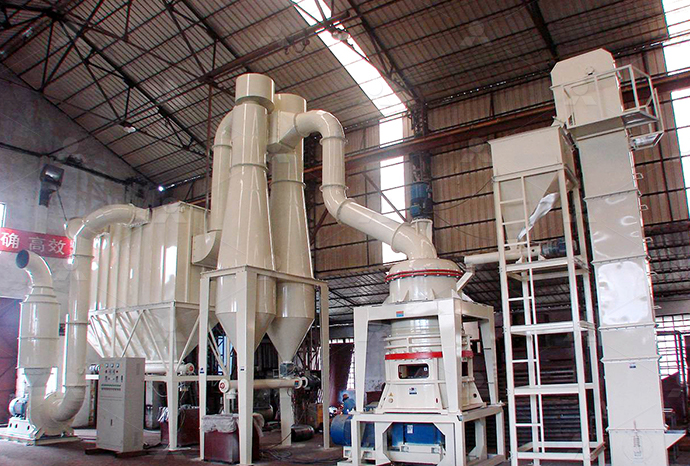
MTW European Type Trapezium Mill
Input size:30-50mm
Capacity: 3-50t/h
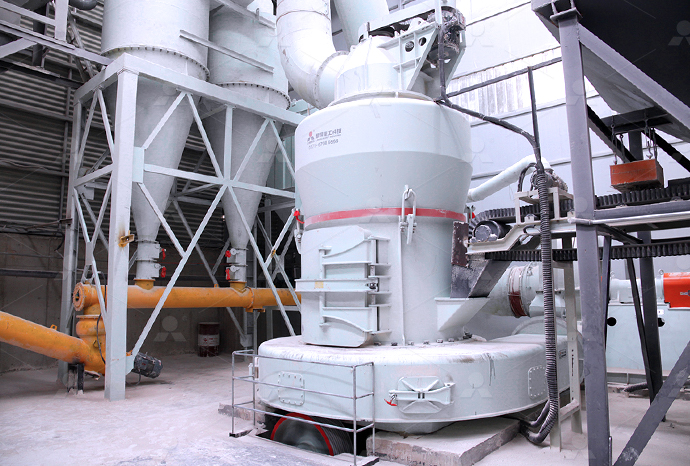
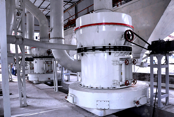
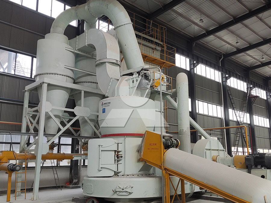
LM Vertical Roller Mill
Input size:38-65mm
Capacity: 13-70t/h
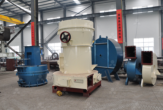
Raymond Mill
Input size:20-30mm
Capacity: 0.8-9.5t/h

Sand powder vertical mill
Input size:30-55mm
Capacity: 30-900t/h

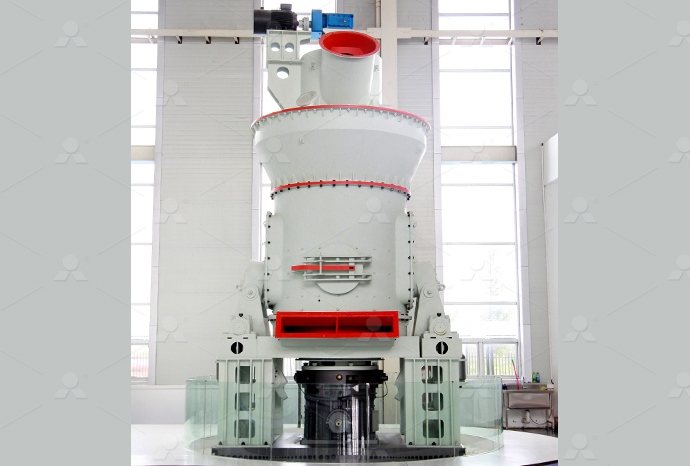
LUM series superfine vertical roller grinding mill
Input size:10-20mm
Capacity: 5-18t/h
MW Micro Powder Mill
Input size:≤20mm
Capacity: 0.5-12t/h

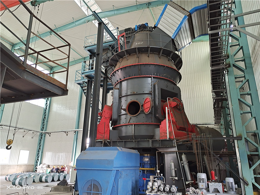
LM Vertical Slag Mill
Input size:38-65mm
Capacity: 7-100t/h

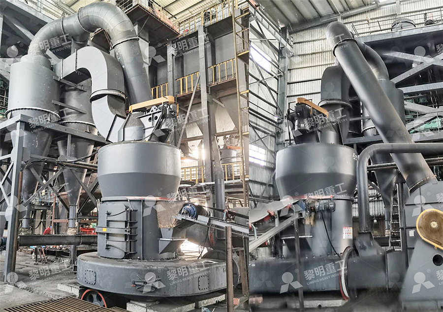
LM Vertical Coal Mill
Input size:≤50mm
Capacity: 5-100t/h
TGM Trapezium Mill
Input size:25-40mm
Capacity: 3-36t/h

MB5X Pendulum Roller Grinding Mill
Input size:25-55mm
Capacity: 4-100t/h

Straight-Through Centrifugal Mill
Input size:30-40mm
Capacity: 15-45t/h
How to calculate the ratio when 3 live wires are connected to 3 transformers

Delta Connection (Δ): 3 Phase Power, Voltage Current Values
It is seen in fig 2 that there is only one phase winding between two terminals (ie there is one phase winding between two wires) Therefore, in Delta 展开2016年9月19日 The transformation ratio is calculated as equal to the ratio between the main primary and secondary voltages with no load independently of the ratio between the numbers Threephase transformer connections and vector groups for There are various methods available for transforming 3phase voltages to higher or lower 3phase voltages ie for handling a considerable amount of power The most common connections are TRANSFORMER: THREE PHASE nitedu2004年11月1日 Because each line from a delta configured transformer is connected to two transformer phases, the line current from a 3phase load will be greater than the phase current Understanding the Basics of Delta Transformer Calculations
.jpg)
Easy understanding of 3phase transformer connections (Delta
2017年7月14日 Balanced loading requires the selection of three transformers with equal voltage ratios and identical impedances Also, the amount of singlephase load should be kept low Threephase ThreeWire Connection (Two Wattmeter Method) Where three wires are present, two wattmeters are required to measure total power Connect the wattmeters as shown in Basic threephase power measurements explained IAEI Magazine2021年8月29日 To calculate voltage in star connection, we consider a threephase fourwire configuration as shown in the above star connection figure According to Kirchhoff’s law, we Threephase Transformer Connections (Wiring Diagrams Included)2023年11月15日 When connected to a threephase line voltage of 100 V, the voltage across each transformer H winding is the same as the threephase line voltage, and as a result, the Making Sense of the Fundamentals and Configurations of 3Phase
.jpg)
Transformer calculator full load current and turns ratio
Calculate the secondary full load current of a 200 kVA, 11 kV to 420 V, stepdown transformer The transformer calculator calculates the primary and secondary full load current, and turns conduits, relays, fuses, circuit breakers, transformers and the like Furthermore, the calculations of currents are often needed to demonstrate that an installation will be in accordance with applicable codes, as the National Electrical Code (NEC) This course presents the means for calculating currents in the conductors ofCalculating Currents in Balanced and Unbalanced Three Phase bank of 3 transformers connected in Y on both the primary and the secondary sides is shown The ratio of line voltages on the primary and secondary sides is the same as the transformation ratio of each transformer However, there is a phase shift of 30° between the phase voltages and line voltages both on the primary and secondary sidesTRANSFORMER: THREE PHASE niteduLine Voltages and Phase Voltages in Star Connection We know that the Line Voltage between Line 1 and Line 2 (from fig 3a) is V RY = V R – V Y (Vector Difference) Thus, to find vector of V RY, increase the Vector of V Y in reverse Star Connection (Y): 3 Phase Power, Voltage Current
.jpg)
Ratio Calculator Good Calculators
Despite the fact that you cannot enter a ratio of 4/5 into this calculator, it accepts values such as 4:5, for example, 4/3 should be written as 4:3 Moreover, our ratio calculator is also able to write down the list of equivalent ratios and process decimal numbers How to Calculate RatiosTransformers do what their name implies—they transform voltages from one value to another (The term voltage is used rather than emf, because transformers have internal resistance) For example, many cell phones, laptops, video games, and power tools and small appliances have a transformer built into their plugin unit (like that in Figure \(\PageIndex{1}\)) that changes 120 V 2310: Transformers Physics LibreTextsFind out how ratios link two quantities or more, and what it means when numbers are written in the form a:b, with this KS3 Maths guide from BBC BitesizeRatio Ratio and proportion KS3 Maths BBC BitesizeTransformer formula is a very important and useful tool to calculate the Transformer Efficiency, Turn Ratio, and Voltage Stepup/down ratio The transformer has two types of application such as stepup or stepdown circuits which are used for different purposes in homes and industriesTransformer Formula Efficiency, Turn Ratio, Step Up and
Understanding the 3 Wire Transformer Wiring Diagram: A
When it comes to wiring a transformer, a 3wire configuration is commonly used This means that there are three wires connected to the transformer: a primary wire, a secondary wire, and a neutral wire2019年8月14日 A 480 to 208 is a 23 ratio For a 45 KVA transformer the size of the primary side overcurrent device is permitted to be 70 amperes The ampacity of the load side conductors must be a minimum of 1/3 the value of the primary side overcurrent device—or 2334 amperes in this case—multiplied by the primary to secondary voltage ratio of 23The 480/277 V to 208/120 V Wye Transformer Installation IAEI Cuemath is one of the world's leading math learning platforms that offers LIVE 1to1 online math classes for grades K12 Our mission is to transform the way children learn math, The formula for calculating ratios is p:q = p/q and the steps for finding the ratio of 2 numbers are given as follows First, we write the given numbers in the Ratio Formula Examples Ratio Calculations How to Find Ratio?2009年3月1日 It is a three phase generator, each phase supplies 167/3 = 56 kVA Assuming delta connected, the line voltage is across each phase and the current is 56,000/240 = 230 A If it is star connected than the phase voltage is Three Phase Current Simple Calculation myElectrical
.jpg)
How to Calculate Ratios: 9 Steps (with Pictures)
2024年1月29日 1 You add the numbers of the ratio: 2 + 3 = 5 2 You divide the total cost ($175) by 5 175 / 5 = 35 3 You multiply this number by each of the numbers of the ratio: 35 x 2 = 70, and 35 x 3 = 105 Solution: one paid $70, 2018年5月12日 Example Video Questions Lesson Share to Google Classroom Example Video Questions Lesson Share to Google Classroom In this example, we are sharing £50 in the ratio 2:3, using steps Step 1 is to find the total How to Calculate a Ratio of a Number Maths with to a load (Figure 3) The total load is 3 x 100W = 300W To supply the power, 1 amp flows through 6 wires and there are thus 6 units of loss Alternatively, the three supplies can be connected to a common return, as shown in Figure 4 When the load current in each phase is the same the load is said to be balancedThe Fundamentals of ThreePhase Power MeasurementsAssuming an ideal transformer and the phase angles: Φ P ≡ Φ S Note that the order of the numbers when expressing a transformers turns ratio value is very important as the turns ratio 3:1 expresses a very different transformer relationship and output voltage than one in which the turns ratio is given as: 1:3 Transformer Basics Example No1Transformer Basics Basic Electronics Tutorials and Revision
The Complete Guide to Electrical Insulation Testing Instrumart
switch, transformer, etc – is carefully covered with some form of electrical insulation The wire itself is usually copper or aluminum, which is known to be a good conductor of the electric current that powers your equipment The insulation must be just the opposite from a to design the transformer First, calculate the minimum transformer area using Equation (9): A T= @ PP × MP MAX × MP RMS FMAX × 00085 A 4 3 ×10000= @53μ L × 188 × 077 ERMS 02 × 00085 A 4 3 ×10000≈163mm4 (9) B MAX is typically a defined input parameter; for ferrite cores it is generally between 02T and 03T Using the A PHow to Design a Flyback Converter in Seven Steps Monolithic Online transformer turns ratio calculator is used to calculating the turns ratio/voltage ratio/current ratio of the transformer For that first select the value from turns or current or voltage Then enter the primary turns or voltage or current and secondary voltage or current or turs Press the calculate button to get the turns ratio of the Transformer Turns Ratio Calculator With Formula Electrical4u2009年5月1日 This simple calculation results in a value of 277, which you would interpret as an approximate 28:1 ratio The next higher standard PT ratio (see Table 2) is 40:1, and you would choose this ratio PT Verify the selection To make sure you've chosen the PT with the correct ratio, you should calculate its secondary voltageThe Basics of Instrument Transformers — Part 1 ECM
.jpg)
Understanding the Basics of Delta Transformer Calculations
2004年11月1日 Delta transformer current In a delta transformer, the line current doesn't equal the phase current (as it does in a wye transformer) Because each line from a delta configured transformer is connected to two transformer phases, the line current from a 3phase load will be greater than the phase current by the square root of 3 Note these formulas:The key here is whether you have a delta or a Y configuration For 230V line to line it is most likely a delta Most (in the US at least), 3phase systems that are Y connected are 277/480 meaning 277VoltsRMS line to neutral, and Three phase power supply what is line to line voltageAs transformers operate on the principal of mutual induction, each individual winding of a multiple winding transformer supports the same number of volts per turn, therefore the voltampere product in each winding is the same, that is N Multiple Winding Transformer and Multicoil transformer windings, motors and other loads may be connected either in star or delta 82 Star Connection (i) A starconnected load is shown in Figure 83, where the three line conductors are each connected to a load and the outlets from the loads are joined together at N to form what is termed the neutral point or the star pointLECTURE 8: Three Phase Systems Benard Makaa
ShortCircuit Current Calculations
Step 4 Calculate the "f" factor Step6 C alcuhv ib so ry m RM current at the point of fault Add motor contribution, if applicable tepA C al cu h "f or(ISC primary k now ) Step B Calculate "M" (multiplier) Step C Calculate the shortcircuit current at the secondary of the transformer (See Note under Step 3 of "Basic PointtoK Webb ESE 470 2 Power Transformers Transformers are used throughout the electrical grid Step voltages up and down for transmission, distribution, and consumption Located at power stations, substations, along distribution feeders, and at industrial customers exportersindia We’ll first review the fundamentals of ideal transformers,SECTION 3: POWER TRANSFORMERS Oregon State University 2024年11月17日 Inserting these quantities into the formula: N(pri) = 32 We won’t be applying fragmentary winding, therefore we are going to round off N(pri) for the closest whole number, in this particular scenario, let's round it down to 3 turnsHow to Calculate Ferrite Transformer for SMPS Making Easy 2017年5月12日 Current transformers (CTs) are essential components in the monitoring and protection of electrical power systems These instrument transformers are specifically designed to convert high primary currents into lower secondary currents, enabling their utilization with meters, relays, control equipment, and various other instruments By accurately transforming and 6 Electrical Tests for Current Transformers Explained
.jpg)
Deploying Current Transformers in Applications Greater Than 200 A
To find the appropriate current transformer rating, it is impo rtant to multiply the Full Load Amperes (FLA) by a factor of 125 The factor of 125 locates the FLA above 2/3 full scale of the CT, which allows the CT to measure overload conditions See Table 1 to calculate the CT ratio for a 300 Hp, 480V AC motor in the following example:\$\dfrac{40\times 3}{07}\$ = 171 turns can a sanity check be done on this I'm thinking? I could estimate the cross section of the transformer core at 01m\$^2\$ Then I could calculate reluctance of the core based on this formula: Reluctance = \$\dfrac{effective\space length}{permeability\cdot effective\space area}\$How to find the exact number of turns for a power transformer2013年6月15日 hi, i have connected current transformers to the 3 phase kilowatt hour meter as per manufacturers brochure ie 3 wires , one from s1 to kwh meter , one wire from s2 to kwh, and third wire live phase wire to the central pin of the kwh meter How To Connect Current Transformers? EEPThe wires are carried to the external circuit, giving threephase, threewire star connected systems However, sometimes a fourth wire is carried from the star point to the external circuit, called neutral wire, forming threephase, fourwire Star Connection in a 3 Phase System Circuit Globe
.jpg)
How to Calculate Ratios GeeksforGeeks
2024年4月27日 So, the ratio of boys to girls in the classroom is 3:2 How to Calculate Ratios To calculate a ratio, divide one quantity by another and simplify the fraction if possible This shows how many times one quantity is compared to another Make sure both quantities are in the same units before you start2024年8月14日 Toroidal inductors The prior discussion assumed μ filled all space If μ is restricted to the interior of a solenoid, L is diminished significantly, but coils wound on a highμ toroid, a donutshaped structure as illustrated in 32: Inductors and Transformers Physics LibreTexts2017年1月13日 Figure 7 – Delta connection – three phase, three wires Go back to Three phase power measurements ↑ Wye and Delta comparison The Wye configuration is used to distribute power to everyday singlephase appliances found in the home and office Single phase loads are connected to one leg of the wye between line and neutralBasic three phase power measurements explained in detailsIt is used to calculate the actual current from the meter reading In this case, the CT ratio is 600/5, which means that the primary current is 600 A and the secondary current is 5 A The meter ratio is /5, which means that the meter is connected to the secondary side of the CT and measures 5 A Therefore, the multiplying factor is:CT's and PT's Learn Metering
.jpg)
How to Make Step Down Transformers Homemade Circuit
2023年11月20日 Primary winding Area = Primary turns / Turns per sq cm from Table#1 Calculating Secondary Winding Considering that we have the assumed secondary current rating, we are able to determine the wire size for the secondary winding simply by In this example we need to multiply to get the answer instead of dividing So, 3 amps x 40 = 120 amps If 3 amps are flowing in the secondary side then there should be 120 amps flowing in the primary side Example 3 For the third example let’s incorporate the CT and PT Calculations a How to Guide Learn MeteringAfter all, two load wires connect to \(A'\), not just one By definition, the current flowing through that wire is the line current, and therefore in a deltadelta configuration, the line current is not the same as the source or load currents To avoid confusion, 93: ThreePhase Connections Engineering LibreTextsThe transformer calculator calculates the primary and secondary full load current, and turns ratio, of a single or 3phase transformer Includes formulas and examplesTransformer calculator full load current and turns ratio
12012 Center Tapped Transformer Components101
2021年2月27日 The operation and theory behind a Center tapped transformer is similar to a normal secondary transformer These are the input wires for the transformer, it is connected to the phase and neutral of AC mains 2 Using the turns ratio formulae we can calculate the secondary voltage as: